3D printing management: things to note when they get the best results

Optimal Orientation

Mastering Build Orientation: The Key to High-Quality 3D Prints Imagine spending hours designing a perfect 3D model only to have it warp, split, or fail mid-print. Often, the culprit isn’t your design or printer—it’s improper build orientation. This fundamental yet frequently overlooked aspect of 3D printing significantly impacts structural integrity, surface quality, and manufacturing efficiency. […]

CNC Content Navigation

Mastering Build Orientation: The Key to High-Quality 3D Prints

Imagine spending hours designing a perfect 3D model only to have it warp, split, or fail mid-print. Often, the culprit isn’t your design or printer—it’s improper build orientation. This fundamental yet frequently overlooked aspect of 3D printing significantly impacts structural integrity, surface quality, and manufacturing efficiency. Let’s explore how strategic part orientation transforms printing outcomes.

Why Build Orientation Matters

Build orientation refers to how your 3D model is positioned relative to the print bed during fabrication. This seemingly simple decision cascades through every aspect of a print:

  • Structural strength along layer lines
  • Surface finish quality
  • Support material requirements
  • Print time and material usage
  • Dimensional accuracy of critical features

Neglecting orientation optimization often leads to failed prints, wasted resources, and frustration.

Core Principles of Build Orientation Strategy

1. Maximizing Bed Adhesion and Stability

Flat, Broad Surfaces = Foundation Security
Prioritize orientations that maximize contact with the build plate. Larger contact areas improve bed adhesion and prevent warping. Avoid orientations requiring rafts or brims unless unavoidable, as these add post-processing work. Always ask: "Which surface provides the most stable foundation?"

2. Aligning with Mechanical Stress Directions

Layer Line Vulnerability
Printed parts exhibit anisotropic strength—weaker along the Z-axis where layers bond. Orient parts so the primary stress direction runs perpendicular to layer lines. For load-bearing components, position the highest stress vectors parallel to the XY plane to leverage maximum material strength.

3. Respecting Printer Volume Constraints

Reality-Check Your Build Space
Before optimizing for other factors, verify the part fits your printer in the chosen orientation. Tall vertical orientations might exceed Z-axis limits. For batch printing, rotate parts to maximize platform utilization—sometimes a 45-degree angle yields higher density packing.

4. Strategic Reduction of Support Structures

The Support Minimization Calculus
Supports increase material costs, extend print times, and leave surface imperfections. Follow these tactics:

  • Orient to keep overhangs under 45° whenever possible
  • Position complex geometries toward the build plate
  • Isolate high-detail surfaces away from support contact
    Pro Tip: Use tree supports in slicers for difficult geometries—they’re easier to remove and waste less material.

5. Preserving Dimensional Accuracy

Critical Features First
Identify toleranced features (holes, mating surfaces) and orient them optimally:

  • Holes: Print vertically for perfect circularity
  • Flat Surfaces: Orient parallel to XY plane to avoid "stair-stepping"
  • Fine Details: Position away from support contact zones

6. Balancing Print Time and Post-Processing

Time vs. Finish Tradeoffs
Shorter print orientations often come with compromises:

  • Fast prints may require more supports
  • Support-free orientations might extend Z-height and increase time
    Calculate the removal and finishing effort into your decision—a 30-minute time saving isn’t worth hours of sanding.

Real-World Orientation Case Studies

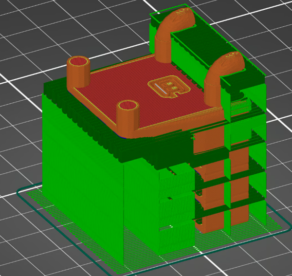
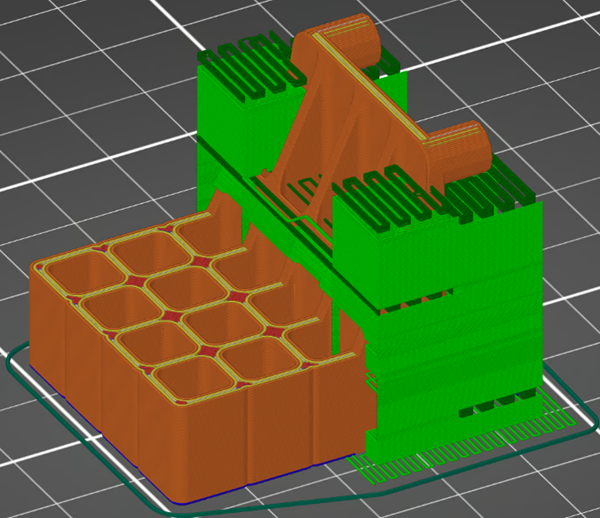
Case 1: The Horizontal Workholder (Optimal)

Optimal Orientation
Dimensional precision achieved through vertical hole orientation (Source: Mark Vanhorne, All3DP)

Configuration:
Part printed flat with maximum bed contact

Performance Analysis:

  • Bed Adhesion: Excellent (large surface area)
  • Strength: Stress perpendicular to Z-axis
  • ⏱️ Time: 268 min (only 19 min supports)
  • 🏗️ Supports: Minimal—confined to tool-holes
  • 🔧 Post-Processing: Easy removal with smooth functional surfaces
  • 🎯 Critical Features: Holes printed vertically for precision

Verdict: Ideal for functional parts requiring precision and strength.

Case 2: Y-Axis Rotation (Time-Saver)

Time-Efficient Orientation
Reduced Z-height minimizes print time (Source: Mark Vanhorne, All3DP)

Configuration:
90° rotation around Y-axis

Performance Analysis:

  • Time: Fastest (226 min total)
  • Supports: 57 min—cover tool holes and pins
  • ⚠️ Surface Finish: Supports leave marks on functional areas
  • 📏 Precision: Horizontal holes less dimensionally accurate
  • 🤔 Tradeoff: Time saved now costs extra finishing later

Best For: Non-critical prototypes needing rapid iteration.

Case 3: X-Axis Rotation (Structural Risk)

High-Support Orientation
Significant support requirement increases post-processing (Source: Mark Vanhorne, All3DP)

Configuration:
90° rotation around X-axis

Performance Analysis:

  • ⚠️ Adhesion: Small contact area requires substantial supports
  • 🚫 Strength: Critical stress parallel to Z-axis (weakest plane)
  • ⏱️ Time: 250 min (62 min supports)
  • 🔨 Post-Processing: Extensive support removal and finishing
  • ⚙️ Precision: Pins accurate but holes compromised

Use Case: Avoid unless specific feature alignment demands it.

Advanced Orientation Tactics

  • Adaptive Angles: For complex geometries, use 15-30° angles to reduce supports while maintaining strength
  • Feature Splitting: Cut models into sub-components for optimal individual orientation
  • Variable Layer Heights: Combine thicker layers for solid sections with fine layers for critical details
  • Thermal Simulation: For industrial applications, simulate thermal stresses in different orientations

Orientation Optimization Workflow

  1. Identify Critical Features: What must be dimensionally perfect?
  2. Determine Stress Vectors: How will the part be loaded?
  3. Test Virtual Placements: Use slicer previews to compare alternatives
  4. Calculate Cost/Benefit: Weigh time, supports, and finishing needs
  5. Prototype Key Options: Print critical portions to validate

The Future of Orientation Optimization

Emerging solutions are automating orientation decisions:

  • AI-Driven Slicers: Machine learning algorithms predicting optimal placement
  • Topology-Aware Systems: Software considering internal stress distributions
  • Multi-Axis Printers: Machines that dynamically reorient parts during printing

Comparative Analysis
Strategic orientation comparison (Source: Mark Vanhorne, All3DP)

Conclusion: Precision Through Positioning

Build orientation is the silent architect of successful 3D printing. As demonstrated in our case studies, optimal orientation (like Case 1) consistently delivers superior mechanical properties, surface quality, and efficiency.

Key takeaways for your next project:

  • Always prioritize functional requirements over convenience
  • Treat orientation as a design parameter—not just a slicing step
  • When in doubt, default to orientations maximizing bed contact
  • For mission-critical parts, prototype multiple orientations

Remember: The best orientation reduces failures while minimizing secondary operations. Master this variable, and you unlock dramatically improved 3D printing economics and part performance.

CNC Experts

Picture of JinShui Chen

JinShui Chen

Rapid Prototyping & Rapid Manufacturing Expert

Specialize in CNC machining, 3D printing, urethane casting, rapid tooling, injection molding, metal casting, sheet metal and extrusion

CNC Recent Posts

CNC News

Common CNC Machining Products

Welcome to GreatLight Metal,Maximum Processing Size 4,000 mm

Precision Machining CNC Quote Online

Loading file

Upload Click here to upload or drag and drop your model to the canvas.

The model is too large and has been resized to fit in the printer's build tray. [Hide]

The model is too large to fit in the printer's build tray. [Hide]

The model is too large, a fitting printer is selected. [Hide]

The model is too small and has been upscaled. [Hide]

Warning: The selected printer can not print in full color [Hide]

Warning: obj models with multiple meshes are not yet supported [Hide]

Warning: Unsupported DXF entity  [Hide]

Warning: could not arrange models [Hide]


File Unit:      
Scale:
%
L × W × H:
X: × Y: × Z:  cm 
Rotation:
X: ° Y: °  


Model Stats:

Material Volume: cm3
Support Material Volume: cm3
Box Volume: cm3
Surface Area: cm2
Model Weight: g
Model Dimensions:
x x cm
Number of Polygons:
Number of Shapes:
Total Path: cm
⚡ Instant Quote for Precision Manufacturing

Submit your design files (STEP/IGES/DWG) and receive a competitive quote within 1 hour, backed by ISO 9001-certified quality assurance.

📋 How It Works

  1. Upload & SpecifyShare your 3D model and select materials (Aluminum/Stainless Steel/Titanium/PEEK), tolerances (±0.002mm), and surface treatments.

  2. AI-Powered AnalysisOur system calculates optimal machining strategy and cost based on 10+ years of automotive/aerospace data.

  3. Review & ConfirmGet a detailed breakdown including:
    - Volume pricing tiers (1-10,000+ units)
    - Lead time (3-7 days standard)
    - DFM feedback for cost optimization

Unit Price: 

Loading price
5 Axis CNC Machining Equipment
4 Axis CNC Machining Equipment
3 Axis CNC Machining Equipment
CNC Milling & Turning Equipment
Prototype and Short-Run Injection Moldings Exact plastic material as final design
Volume Metal Die Casting Services - Precision Cast Parts
Bridge the Gap From Prototype to Production – Global delivery in 10 days or less
Custom high-precision sheet metal prototypes and parts, as fast as 5 days.
Custom Online 3D Printing Services
Design Best Processing Method According To 3D Drawings
Alloys Aluminum 6061, 6061-T6 Aluminum 2024 Aluminum 5052 Aluminum 5083 Aluminum 6063 Aluminum 6082 Aluminum 7075, 7075-T6 Aluminum ADC12 (A380)
Alloys Brass C27400 Brass C28000 Brass C36000
Alloys Stainless Steel SUS201 Stainless Steel SUS303 Stainless Steel SUS 304 Stainless Steel SUS316 Stainless Steel SUS316L Stainless Steel SUS420 Stainless Steel SUS430 Stainless Steel SUS431 Stainless Steel SUS440C Stainless Steel SUS630/17-4PH Stainless Steel AISI 304
Inconel718
Carbon Fiber
Tool Steel
Mold Steel
Alloys Titanium Alloy TA1 Titanium Alloy TA2 Titanium Alloy TC4/Ti-6Al 4V
Alloys Steel 1018, 1020, 1025, 1045, 1215, 4130, 4140, 4340, 5140, A36 Die steel Alloy steel Chisel tool steel Spring steel High speed steel Cold rolled steel Bearing steel SPCC
Alloys Copper C101(T2) Copper C103(T1) Copper C103(TU2) Copper C110(TU0) Beryllium Copper
Alloys Magnesium Alloy AZ31B Magnesium Alloy AZ91D
Low Carbon Steel
Alloys Magnesium Alloy AZ31B Magnesium Alloy AZ91D
ABS Beige(Natural) ABS Black ABS Black Antistatic ABS Milky White ABS+PC Black ABS+PC White
PC Black PC Transparent PC White PC Yellowish White PC+GF30 Black
PMMA Black PMMA Transparent PMMA White
PA(Nylon) Blue PA6 (Nylon)+GF15 Black PA6 (Nylon)+GF30 Black PA66 (Nylon) Beige(Natural) PA66 (Nylon) Black
PE Black PE White
PEEK Beige(Natural) PEEK Black
PP Black PP White PP+GF30 Black
HDPE Black HDPE White
HIPS Board White
LDPE White
This is a finish of applying powdered paint to the components and then baking it in an oven, which results in a stronger, more wear- and corrosion-resistant layer that is more durable than traditional painting methods.
No coating required, product’s natural color!
This is a finish of applying powdered paint to the components and then baking it in an oven, which results in a stronger, more wear- and corrosion-resistant layer that is more durable than traditional painting methods.
This finishing option with the shortest turnaround time. Parts have visible tool marks and potentially sharp edges and burrs, which can be removed upon request.
Sand blasting uses pressurized sand or other media to clean and texture the surface, creating a uniform, matte finish.
Polishing is the process of creating a smooth and shiny surface by rubbing it or by applying a chemical treatmen
A brushed finish creates a unidirectional satin texture, reducing the visibility of marks and scratches on the surface.
Anodizing increases corrosion resistance and wear properties, while allowing for color dyeing, ideal for aluminum parts.
Black oxide is a conversion coating that is used on steels to improve corrosion resistance and minimize light reflection.
Electroplating bonds a thin metal layer onto parts, improving wear resistance, corrosion resistance, and surface conductivity.
This is a finish of applying powdered paint to the components and then baking it in an oven, which results in a stronger, more wear- and corrosion-resistant layer that is more durable than traditional painting methods.
Please provide additional text description for other surface treatment requirements!
Material
Material
  • CNC Metals
    • Aluminum
    • Brass
    • Stainless steel
    • Inconel718
    • Carbon Fiber
    • Tool Steel
    • Mold Steel
    • Titanium
    • Alloy Steel
    • Copper
    • Bronze
    • Low Carbon Steel
    • Magnesium
  • CNC Plastics
    • ABS
    • PC
    • PMMA (Acrylic)
    • PA (Nylon)
    • PE
    • PEEK
    • PP
    • HDPE
    • HIPS
    • LDPE
Printer
Printer
  • CNC Metals
    • 5 Axis CNC Machining
    • 4 Axis CNC Machining
    • 3 Axis CNC Machining
    • CNC Milling & Turning
    • Rapid Tooling
    • Metal Die Casting
    • Vacuum Casting
    • Sheet Metal Fabrication
    • SLA 3D Printing
    • SLS 3D Printing
    • SLM 3D Printing
  • Rapid Prototyping
    • Design Best Processing Method According To 3D Drawings
Post-processing
Post-processing
Finalize
The world's first CNC machining center that dares to provide free samples!

Free for first product valued at less than $200. (Background check required)

precision machining cnc quote online

15 Years CNC Machining Services

When you’re ready to start your next project, simply upload your 3D CAD design files, and our engineers will get back to you with a quote as soon as possible.
Scroll to Top

ISO 9001 Certificate

ISO 9001 is defined as the internationally recognized standard for Quality Management Systems (QMS). It is by far the most mature quality framework in the world. More than 1 million certificates were issued to organizations in 178 countries. ISO 9001 sets standards not only for the quality management system, but also for the overall management system. It helps organizations achieve success by improving customer satisfaction, employee motivation, and continuous improvement. * The ISO certificate is issued in the name of FS.com LIMITED and applied to all the products sold on FS website.
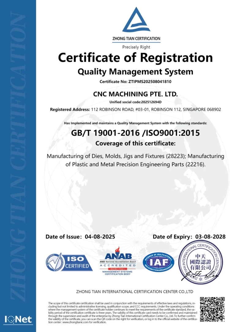
greatlight metal iso 9001 certification successfully renewed
GB T 19001-2016 IS09001-2015
✅ iso 9001:2015
greatlight metal iso 9001 certification successfully renewed zh

ISO 13485 certificate

ISO 13485 is an internationally recognized standard for Quality Management Systems (QMS) specifically tailored for the medical device industry. It outlines the requirements for organizations involved in the design, development, production, installation, and servicing of medical devices, ensuring they consistently meet regulatory requirements and customer needs. Essentially, it's a framework for medical device companies to build and maintain robust QMS processes, ultimately enhancing patient safety and device quality.

greatlight metal technology co., ltd has obtained multiple certifications (3)
greatlight metal technology co., ltd has obtained multiple certifications (4)

ISO 27001 certificate

ISO/IEC 27001 is an international standard for managing and processing information security. This standard is jointly developed by the International Organization for Standardization (ISO) and the International Electrotechnical Commission (IEC). It sets out requirements for establishing, implementing, maintaining, and continually improving an information security management system (ISMS). Ensuring the confidentiality, integrity, and availability of organizational information assets, obtaining an ISO 27001 certificate means that the enterprise has passed the audit conducted by a certification body, proving that its information security management system has met the requirements of the international standard.

greatlight metal technology co., ltd has obtained multiple certifications (1)
greatlight metal technology co., ltd has obtained multiple certifications (2)

IATF 16949 certificate

IATF 16949 is an internationally recognized Quality Management System (QMS) standard specifically for the automotive industry. It builds upon the foundation of ISO 9001 and adds specific requirements relevant to automotive production and service parts. The goal is to enhance quality, improve processes, and reduce variation and waste within the automotive supply chain.

automotive industry quality management system certification 01
automotive industry quality management system certification 00

Get The Best Price

Send drawings and detailed requirements via Email:info@glcncmachining.com
Or Fill Out The Contact Form Below:

All uploads are secure and confidential.