
How a Speed Composite Machining Center Machines Complex Parts in One Setup
A speed composite machining center combines turning and milling on one platform, so a part that needs three setups on separate machines comes off complete in one clamping. This page explains the mechanics, the accuracy you can expect, and the part geometries where the approach stops making sense.
What a Speed Composite Machining Center Actually Does
A speed composite machining center holds the workpiece in a spindle or chuck and moves a milling tool around it on multiple linear and rotary axes. The turning spindle and the milling spindle share one structure, so the machine can face, turn, drill, tap, and mill without releasing the part. That single structure is the whole point. Every time a part moves between machines, the datum shifts a little.
On a conventional route, a turned shaft goes from a lathe to a vertical mill, then to a drill press. Each move needs a new fixture, a new zero point, and a new first-article check. Stack three setups and the tolerance budget has to absorb three sources of position error. A composite center removes two of those handoffs. The remaining error is mostly thermal drift and tool wear, which are predictable and measurable.
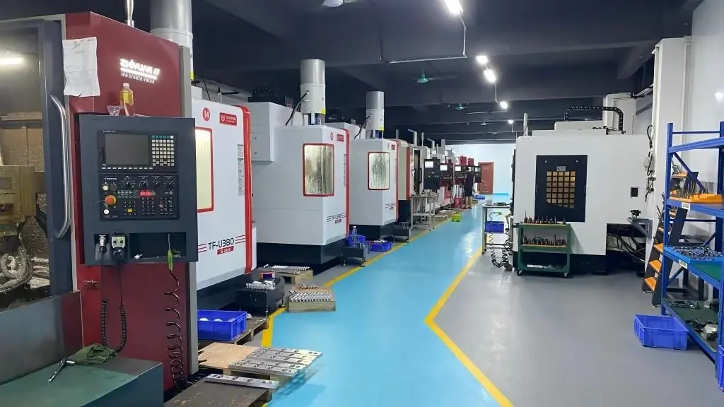
The milling head usually carries a live tool or a full B-axis. A B-axis head tilts the tool relative to the part, which lets the machine cut angled holes, undercuts, and contoured pockets that a fixed tool cannot reach. On our 16 mill-turn centers, the rotary table reaches Ø400 mm, and the largest platform handles parts up to 4,000 mm long. That covers most shaft-type parts, valve bodies, and manifold blocks.
Speed matters here, but not in the way the name suggests. High spindle speed shortens cycle time on small tools and light cuts. The bigger gain comes from eliminating setup time and queue time between operations. For a part with four operations, dropping from four setups to one often cuts total lead time by more than half, even if each individual cut runs at the same feed.
- 1One clamping, multiple operationsTurning, milling, drilling, and tapping share the same zero point.
- 2B-axis milling headTilts the tool for angled holes and contoured pockets.
- 3Live toolingCuts off-axis features while the part stays in the chuck.
- 4Bar feeder or gantryKeeps small parts running unattended through the night.
Where the Accuracy Comes From, and Where It Leaks
Tolerance on a well-maintained composite center sits around ±0.005 mm on turned diameters and milled features, with surface finish between Ra 0.8 and 1.6 μm on most alloys. Getting there depends less on the machine spec sheet and more on how the process is controlled. Thermal growth is the first thing to manage. A spindle that runs for two hours is not the same size as a spindle that just started.
We handle this by letting the machine warm up on a known test part before production, then holding the same spindle load through the run. In-process probing corrects for drift between parts. On a 4,000 mm shaft, a 2 °C shop swing can move the far end by more than 0.01 mm, so temperature control in the bay matters as much as the ballscrew grade.
Tool wear is the second source. A finishing insert that has cut 200 parts does not hold the same diameter as a fresh one. For runs above a few hundred pieces, we log tool life and change on a count rather than waiting for a dimension to drift out. That is cheaper than scrapping parts at final inspection.
The third source is the fixture. A three-jaw chuck grips a round part with some runout. A collet or a dedicated soft jaw holds it better. When concentricity between a turned diameter and a milled bore matters, the order of operations decides the result. Cut the datum first, then everything that references it, without moving the part.
Which Part Geometries Belong on This Machine
The strongest fit is a part with a rotational axis plus off-axis features. Think of a hydraulic manifold with a turned body and cross-drilled ports, or a motor housing with a bored center and a bolt circle. The rotational axis gives the machine something to spin, and the off-axis features give it something to mill. Both run in the same setup.
The second good fit is anything with tight positional relationships between features on different faces. If a bore on one end must be concentric with a bore on the other end, doing both in one clamping removes the error that comes from re-chucking. This is common in pump housings, spindles, and gear blanks.
The third fit is small to medium parts made in volume. A bar feeder can run a family of fittings or connectors unattended. Setup time spreads over thousands of parts, so the economics improve quickly. Our minimum order quantity is one piece, but the cost curve really bends at a few hundred.
The weak fit is a flat, prismatic part with no rotational axis. A block with pockets on two faces has nothing for the turning spindle to do. A 3-axis or 5-axis mill will cut it faster and simpler. Putting that part on a composite center wastes the turning capability and adds fixturing that does not help.
- 1Good fitRotational body plus cross-features, in one setup.
- 2Good fitConcentric bores on opposite ends of the same part.
- 3Good fitHigh-volume small parts on a bar feeder.
- 4Poor fitFlat prismatic plates with no turned features.
Boundary Conditions: When the Composite Route Loses
A composite center is not always the cheap answer. If a part has only one operation, the dedicated machine usually wins. A simple turned bushing with no milled features runs faster on a lathe with a bar feeder, and the hourly rate is lower. Do not pay for capability you will not use.
Very large parts are another limit. Our largest platform reaches 4,000 mm, but a casting that needs a 6 m bed will not fit. At that size, the part usually goes to a large gantry mill, and turning features are handled separately or not at all.
Deep bores with a high length-to-diameter ratio can also be a problem. A boring bar that needs to reach 10× diameter will chatter before it cuts cleanly. On a composite center, the part can spin while a stationary tool bores, which helps, but there is a limit. Past roughly 8× diameter, we look at honing or a dedicated deep-hole machine.
Material matters too. Titanium and Inconel cut slower and generate more heat, so cycle times stretch. The one-setup advantage still holds, but the cost per part rises. For a single prototype in Inconel, the setup saving may not cover the slower cutting. For a run of 500, it usually does.
Composite Center vs. Separate Turn and Mill Operations
Use this table to decide which route fits a specific part.
| Factor | Speed composite machining center | Separate turn then mill |
|---|---|---|
| Number of setups | One | Two or more |
| Positional error sources | Thermal drift and tool wear | Adds re-chucking error per setup |
| Best part shape | Rotational body with off-axis features | Simple turned parts or flat plates |
| Volume sweet spot | A few hundred to 10,000+ parts | One-off or very simple geometry |
| Typical tolerance | ±0.005 mm | ±0.01 mm or looser across setups |
| Lead time driver | Cycle time only after first setup | Queue time between machines |
| Hourly rate | Higher | Lower |
| Unattended running | Bar feeder, lights-out capable | Limited by manual transfers |
The Short Version
If the part has a rotational axis and any off-axis feature, run it on a speed composite machining center. If it is a flat plate or a plain turned bushing with nothing else on it, a separate lathe and mill will cost less.
Common Questions
Does one setup really hold ±0.005 mm across a long part?
Yes, when the machine is warm and the process is controlled. The tolerance applies to features cut in the same clamping. On a 4,000 mm part, thermal growth over the length is the limiting factor, so we hold shop temperature and probe in process.
If a feature must be cut in a second setup, the budget loosens. Plan on ±0.01 mm for anything that crosses a re-chuck.
What materials run well on a composite center?
Aluminum alloys such as 6061, 7075, and 2024 cut fast and hold tight tolerance. Stainless 303, 304, 316L, and 17-4PH also run well, with more tool wear. Titanium TC4 and Inconel cut slower but still benefit from the one-setup approach.
Plastics like POM, PEEK, and ABS are fine for prototypes, though clamping pressure needs care to avoid deformation.
How does the machine handle a part that needs a deep bore?
The part can spin while a stationary tool bores, which reduces chatter compared with a rotating tool. Past roughly 8× diameter, we switch to a dedicated deep-hole process or add honing after machining.
Tell us the bore depth and diameter at quoting so we can pick the right route.
Can I get one prototype before committing to a run?
Yes. There is no minimum order quantity, and we run from one piece to 10,000+ parts. For a first article, we quote and return a DFM analysis within 12 hours, and production can start within 24 hours of approval.
Prototypes ship in 3–5 days for most geometries.
What surface finish should I expect?
As-machined finish lands between Ra 1.6 and 3.2 μm. With a finishing pass and the right insert, we reach Ra 0.8–1.6 μm. Fine finishing on turned diameters can reach Ra 0.2–0.8 μm.
If the drawing calls for a specific Ra, put it on the print so the tool path and feed are set for it.
How do you keep the process stable over a long run?
We warm up the spindle on a test part, hold a steady load through the run, and probe between parts to correct drift. Tool changes are logged by count, not by waiting for a dimension to go out.
Every part gets inspected before shipment, and reports are available on request.
Send the Drawing, Get a Route
Upload your part and we will tell you whether it belongs on a speed composite machining center or a simpler machine, with a quote and DFM notes in 12 hours.
12-hour quote100% inspectionNo minimum order quantity
More from GreatLight
We publish setup notes, tooling trials and inspection data from the factory floor.











