
01
A bore that drifts out of position
Re-fixturing a housing across three setups stacks positional error. Two bores that should share an axis end up 0.03 mm apart, the bearing preload changes, and the assembly whines at speed.
We machine engine brackets, housings, mounts and driveline parts from your 3D files. Sixteen simultaneous 5-axis centers, ±0.005 mm, prototypes through 10,000+ part runs.
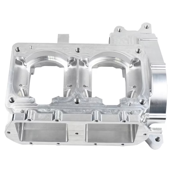
Most failures trace back to a process decision made before the first chip.
Re-fixturing a housing across three setups stacks positional error. Two bores that should share an axis end up 0.03 mm apart, the bearing preload changes, and the assembly whines at speed.
Wrong alloy or a tool path that leaves sharp internal corners. Vibration fatigue starts at the corner and the part fails well before the warranty period ends.
The prototype was hand-finished on a single setup. Once the part moves to a production fixture, wall thickness and hole locations shift, and the first article no longer fits the mating assembly.
Two weeks of email back and forth over a drawing that should take ten minutes to review. The program slips, and the engine dyno slot you booked gets handed to another team.
Five-axis work removes the error that comes from moving a part between machines.
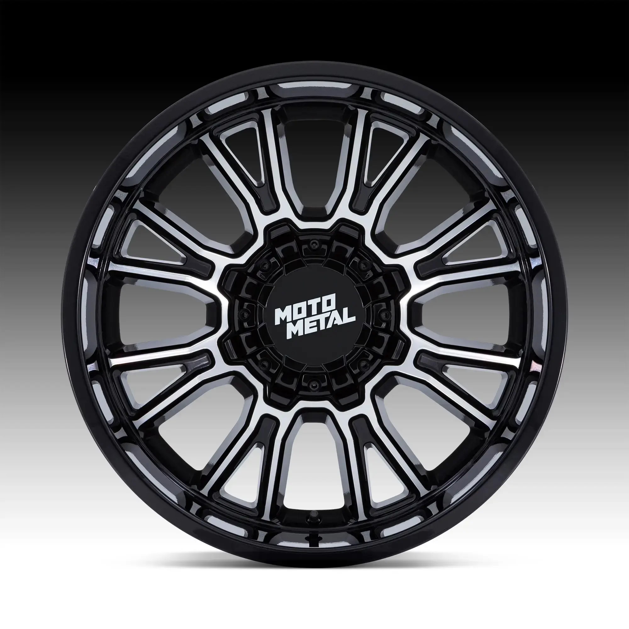
A timing cover or a transmission housing usually has bores on two or three faces plus a sealing surface that has to stay flat. On a 3-axis mill that means three fixtures and three datums. Every re-clamp adds a small positional error, and small errors add up across a 300 mm casting.
We hold these parts on a Ø400 mm rotary table in one of the sixteen simultaneous 5-axis centers. The part rotates, the tool stays in its sweet spot, and all critical bores come off the same datum. The practical result is that a bore pattern stays concentric to the main axis instead of fighting it.
Cycle time usually drops as well, because the tool reaches the back face without a second operation. For a cover with 40 tapped holes, that is the difference between two days and half a day of machine time.
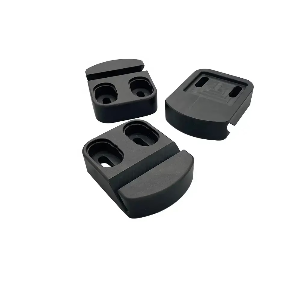
Engine-side parts are rarely simple aluminum. A 4140 mount, a 17-4PH sensor boss, or a Ti-6Al-4V flange brings its own rules. Heat goes into the part during roughing, the part moves, and the finishing pass cuts a shape that no longer matches the model.
We rough with stock left on, let the part settle, then take the finishing cuts after the coolant has brought it back to room temperature. For hardened or stress-relieved stock we plan the sequence around the heat treat, not around the machine schedule. A 1045 shaft that will be induction hardened gets its bearing journals ground after hardening, not before.
Titanium needs lower surface speed and more coolant. Push it and the tool edge breaks down, which shows up as chatter marks on a sealing face. We keep dedicated tooling for titanium and Inconel so the feeds stay conservative and the finish stays predictable.
A quick read on when five-axis pays off and when it does not.
| Part type | Recommended process | Why |
|---|---|---|
| Bracket, flat plate, 2 faces | 3-axis milling | Fewer setups, lower hourly rate |
| Housing with bores on 3 faces | 5-axis simultaneous | One datum, no re-clamp error |
| Shaft with journals and a flange | Mill-turn | Turning and milling in one cycle |
| Thin-wall cover, 1.5 mm wall | 5-axis, light finishing passes | Less clamping distortion |
| Wheel hub, deep radial pockets | 5-axis with rotary table | Short tools, less deflection |
| Exhaust manifold flange | 3-axis plus surface grinding | Flatness is the critical callout |
Six capabilities that cover most vehicle and engine work.
Complex housings, covers and mounts cut in one clamping on sixteen simultaneous centers.
Shafts, bushings and threaded fittings. Mill-turn centers handle both operations in one cycle.
One-off brackets and test fixtures for fit checks before tooling is committed.
Anodizing, black oxide, zinc plating, bead blasting and laser marking for part IDs.
Brackets, heat shields and covers when a machined part is heavier than it needs to be.
Aluminum housings at higher volume, with post-machining on critical faces.
What we can physically take on, and in which alloys.
| Item | Range | Notes |
|---|---|---|
| Maximum part size | 4,000 × 400 × 150 mm | Largest travel on the long-bed mills |
| Standard envelope | 750 × 1,150 × 550 mm | Most auto parts fall in this range |
| Compact work | 500 × 310 × 200 mm | Small brackets and fittings |
| Tolerance | ±0.005 mm | ±0.0002 in on critical features |
| Surface finish | Ra 0.2–0.8 μm | Ra 0.8–1.6 μm on general faces |
| Aluminum | 6061, 7075, 2024, ADC12 | Plus 5052, 5083, 6082 |
| Stainless | 303, 304, 316L, 17-4PH | 440C and 431 for wear parts |
| Steel | 1018, 1045, 4130, 4140 | 4340 and tool steel on request |
Fifteen years of machining, three plants, and one quality system across all of them.
Fifteen years of production work, most of it on parts where a bore position matters to the assembly.
Dongguan and Singapore sites. All three run the same inspection routine and the same documentation.
Sixteen 5-axis, twelve 4-axis, twenty-seven 3-axis, sixteen mill-turn centers under one roof.
IATF 16949:2016 alongside ISO 9001:2015, ISO 13485:2016 and ISO 27001:2022.
You get a price and a design-for-manufacturing review within twelve hours. Production can start in 24.
One prototype or a 10,000+ part run. Same fixtures, same inspection, same paperwork.
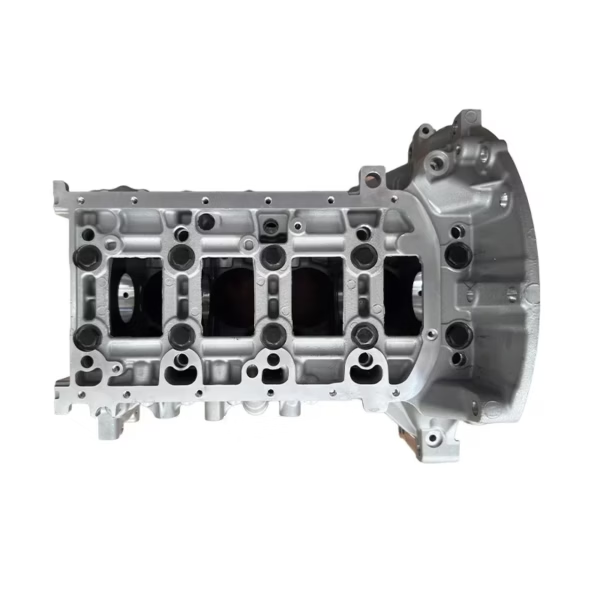
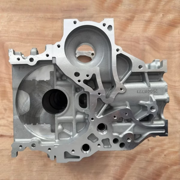
Bore alignment and deck flatness drive the whole assembly fit, so every feature comes off one datum.
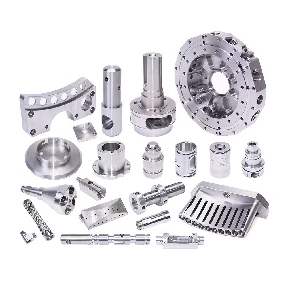
6061-T6 and 7075 with radiused internal corners so vibration fatigue has nowhere to start.
Transition from prototype to a few thousand parts without a fixture change that moves the geometry.
17-4PH and 316L parts with threaded ports and sealing faces that have to hold pressure.
STEP and IGES cover most work. Native SolidWorks, Inventor or Creo files are fine too.
If a part is defined mainly by a drawing, send the PDF alongside the model. Tolerances, surface finish callouts and material specs that live only on the drawing are what we quote against. A model on its own tells us the shape but not how tight you need it.
Aluminum 6061 and 7075, stainless 303 and 316L, and steel 1018 and 1045 are the common ones. We also run 2024, 4130, 4140, 4340, 17-4PH and titanium Ti-6Al-4V.
Magnesium AZ31B and AZ91D are available for weight-critical parts. Plastics such as POM, PA, PEEK and carbon fibre show up in interior and under-hood test parts.
Yes, but the part has to be able to hold it. Thin walls, unsupported bores and soft alloys move under clamping force no matter how good the machine is.
We review this during DFM. If a feature cannot hold ±0.005 mm in production, we say so before quoting and propose either a design change or a realistic tolerance. A tolerance we cannot repeat is worse than a looser one we can.
We machine with stock left on for the hardening step, then finish after the part has been treated and stress-relieved. Hardened surfaces that need tight geometry, such as bearing journals, get ground rather than milled.
This changes the routing and the lead time. We plan the sequence at quote stage so the heat treat does not sit in the middle of the critical finishing operations.
Incoming material is checked against the certificate. In-process checks run at defined points during the cycle, not only at the end. Every part gets a final inspection before it ships.
Dimensional reports, material certificates and first article inspection reports are available on request. We do not ship a batch and inspect afterwards.
Yes. Uploads are handled as confidential, and we can sign your NDA or provide ours before any drawing changes hands.
This matters for parts tied to an unreleased vehicle program. Files are kept inside the project folder and not shared outside the team working on the job.
Quotation and DFM feedback come back within twelve hours. Production can start within 24 hours of approval, and most parts ship in three to five days.
That window assumes the drawing is final and the material is available. Parts needing heat treatment, plating or a custom fixture take longer, and we tell you the real number at quote stage rather than after the order.
Yes. There is no minimum order quantity, so a single bracket is fine. When the design is locked, we keep the same fixture and the same CAM program for the production batch.
That keeps the prototype and the production part dimensionally identical. The most common reason a prototype does not match a production part is that someone re-fixtured it for volume.
Upload a STEP file and a drawing. You get a price and a DFM review within twelve hours, with no minimum order quantity.
12-hour quote100% inspectionNo MOQNDA available
Trusted by engineers and manufacturers worldwide










Upload your 3D model or 2D drawing and get a quotation with a free DFM analysis. Maximum processing size 4,000 mm.
CNC Metals 13 grades
CNC Plastics 10 grades
Machines & processes 12 options
Surface & post-processing 10 options
Material: not selected Machine: not selected Post-process: not selected