
Are You Making These 5 Costly CNC Deckel Maho Mistakes?
Deckel Maho machining centers hold tight geometry, but they punish small process oversights. This page walks through five errors we see on 5-axis work and how to tell whether your shop is making them. Written for engineers and buyers who specify parts at ±0.005 mm.
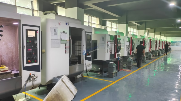
Five Errors That Show Up in the Part, Not in the Program
Each section below describes the mistake, the symptom you can measure, and the fix.
Starting Production Before the Machine Reaches Thermal Equilibrium
A Deckel Maho is built for sub-micron work, and that is exactly why thermal drift hurts it. The spindle, ballscrews, and the casting itself all grow as they warm up. On a cold machine, a feature cut at 07:00 may sit 5–15 μm away from the same feature cut at 11:00. On a hydraulic valve body with a ±0.005 mm bore spacing callout, that is the whole tolerance.
The usual cause is scheduling. A rush job arrives, the operator powers up, homes the axes, and cuts. In high-mix, low-volume work this happens several times a week. The same risk appears when a job is routed through a broker network: the assigned shop may have no documented soak procedure at all, and nobody on your side sees it happen.
The fix is boring but effective. Run a warm-up cycle that exercises the spindle and all rotary axes, hold the coolant at a set temperature, and keep the shop floor stable. On any feature tighter than ±0.010 mm we treat a thermal soak as part of setup, not as optional time. Work that only needs ±0.05 mm usually does not justify the wait.
A simple check: measure a known artifact or a test cut at the start of the shift and again two hours later. If the numbers move, your process is drifting with them.
- 1SymptomFirst parts of a batch pass; later parts drift out of tolerance.
- 2SymptomBore spacing error grows through the morning and stabilizes after lunch.
- 3FixDocumented warm-up cycle plus temperature-controlled coolant.
- 4When to skipFeatures looser than ±0.05 mm rarely need a full soak.
Using the Wrong Toolholder for Simultaneous 5-Axis Cuts
Tilted cutting puts load on a toolholder in directions a 3-axis job never produces. An ER collet chuck that behaves fine in straight Z-axis milling can fret or creep under a tilted roughing pass. The result is micro-deflection, and you see it as poor surface finish on a curved impeller blade or as chatter when peripheral milling titanium.
Toolholder selection should follow the operation, not the shelf. Heavy roughing and long-reach contouring want a stiff interface with high clamping force. Finishing passes on thin walls want low runout more than raw stiffness. Standard collets still have a place in light finishing and in drilling where side load is small.
Balance matters as much as stiffness. A tool assembly balanced to G2.5 at the operating RPM keeps vibration from feeding back into the surface. It also protects the spindle. Toolholders that are fine at 8,000 rpm can be outside spec at 20,000 rpm.
Clearance is the third item, and it is the one that breaks tools. A flange or nut that clears the stock in the CAM view can still strike the workpiece once the rotary table tilts. Check the holder envelope against the actual blank, not the finished part model.
- 1Heavy roughingHigh-clamping interfaces with verified dynamic stiffness.
- 2Thin-wall finishingPrioritize low runout over maximum rigidity.
- 3Long reachShrink-fit or face-contact milling chucks reduce deflection.
- 4Before every 5-axis jobVerify holder clearance against the raw blank.
Treating CAM Simulation as a Formality
Simulation that only shows the toolpath is not simulation. It has to include the holder, the fixture, the raw stock, and the actual machine kinematics. When those are missing, the collision shows up on the machine instead of on the screen.
Complex contours are where this bites. A blade, a combustion chamber liner, or a robot joint housing has surfaces that change curvature continuously. Cut direction, stepover, and lead-in geometry all affect the result. A generic finishing strategy applied to a compound surface leaves witness marks that no amount of polishing removes cleanly.
The practical test is whether the programmer can state the stock condition and the fixture position before posting code. If the answer is vague, the setup will be too. We also keep the post-processor matched to the specific machine, because rotary axis limits and singularity behavior differ between models.
One more point on rest material. On deep pockets with small corner radii, a roughing pass that leaves uneven stock makes the finishing tool load vary along the path. That shows up as a banded surface. Simulating rest material and adding a semi-finish pass costs minutes and saves the part.
- 1Include in simulationHolder, fixture, raw stock, machine kinematics.
- 2Watch forSingularity near rotary axis limits and rapid moves.
- 3Surface qualityMatch cut direction and stepover to the curvature change.
- 4Rest materialUneven roughing stock causes banded finishes on deep pockets.
Skipping Calibration and Preventive Maintenance
A 5-axis machine has more error sources than a 3-axis mill: two rotary axes, their center offsets, and the relationship between them. Geometric errors accumulate quietly. Parts stay close enough for weeks, then a batch runs out of tolerance and the cause is traced to a rotary axis that has shifted.
Rotary center calibration, spindle taper check, and ballscrew backlash measurement should run on a schedule, not after a bad batch. The interval depends on cutting hours and material. Heavy titanium and Inconel work loads the structure harder than aluminium, so it needs shorter intervals.
Coolant and way lubrication belong in the same checklist. Contaminated coolant changes thermal behavior and surface finish. Way lube starvation shows up first as inconsistent positioning on long moves, which is easy to misread as a programming problem.
If your supplier cannot show calibration records on request, that is a signal. Records do not have to be elaborate. A dated log with the measured values is enough to tell whether the machine was drifting and by how much.
- 1Rotary calibrationCheck center offsets and the relationship between the two axes.
- 2BacklashMeasure on all linear axes; watch long moves for inconsistency.
- 3IntervalShorter for titanium and Inconel, longer for aluminium.
- 4Ask forDated calibration logs, not a verbal assurance.
Applying One Cutting Strategy Across Every Material
Aluminium 6061 and Ti-6Al-4V do not share a strategy. Aluminium moves heat into the chip, so the limit is chip evacuation and spindle speed. Titanium keeps heat at the cutting edge, so the limit is edge temperature and tool life. Running both with the same speeds, feeds, and coolant pressure guarantees that one of them is wrong.
Inconel and other nickel alloys go further. They work-harden under a rubbing cut, so a light pass with a dull edge makes the next pass harder. Toolpath strategy has to keep the edge engaged and avoid dwelling.
Stainless grades differ among themselves too. 303 machines cleanly, 316L galls and needs a sharp edge plus generous coolant. Copper and brass cut fast but move with heat, so fixturing and light finishing passes matter more than heavy stock removal.
The material decision is not only about the cut. It sets the finishing route. A part that will be hardcoat anodized needs different edge treatment than one going to electroless nickel, because the coating follows the surface it is given. Decide the finish before the last pass, not after.
- 1AluminiumFocus on chip evacuation and spindle speed.
- 2Titanium and InconelControl edge temperature; avoid dwelling cuts.
- 3StainlessSharp edges and heavy coolant prevent galling on 316L.
- 4Plan aheadChoose the finish before the finishing pass.
Which Condition Sets Your Limit
Match the fix to the failure you actually see.
| Material / feature | Dominant risk | Practical countermeasure |
|---|---|---|
| Aluminium 6061, thin walls | Chatter and wall deflection | Lighter radial engagement, low-runout holder |
| Ti-6Al-4V, deep pockets | Edge heat, short tool life | High-pressure coolant, keep the edge engaged |
| Inconel, contoured surfaces | Work hardening | No dwell passes, sharp edge, rigid setup |
| 316L, sealing faces | Galling and smeared finish | Sharp geometry, generous coolant flow |
| Any part under ±0.010 mm | Thermal drift | Warm-up cycle plus temperature-controlled coolant |
| Long-reach 5-axis contouring | Holder deflection | Stiff interface, balanced to G2.5 at RPM |
Questions Engineers Ask Next
How long does a thermal warm-up actually take?
It depends on the machine size and the shop temperature. A practical method is to run the spindle and rotary axes through a fixed cycle and check a reference feature until the reading stops moving.
We treat the soak as complete only when consecutive checks agree. On features tighter than ±0.005 mm we do not start the first article before that point.
Can I use ER collets on a 5-axis job at all?
Yes, for light finishing and drilling where side load is small. The problem starts with heavy roughing and long-reach contouring, where tilted cutting forces cause micro-deflection.
If surface finish on a curved surface is inconsistent, the holder is one of the first things to check before changing the toolpath.
What tolerance can a Deckel Maho realistically hold?
At GreatLight, our process tolerance is ±0.005 mm (±0.0002 in) and fine finishes reach Ra 0.2–0.8 μm.
Holding that on a production run depends on thermal control, calibration, and the fixture, not on the machine spec sheet alone.
Do I need to specify the raw stock condition in CAM?
Yes. Simulation without the actual stock and fixture position misses collisions and produces uneven rest material.
Uneven roughing stock is a common cause of banded surfaces on deep pockets with small corner radii.
How often should a 5-axis machine be recalibrated?
Cutting hours and material drive the interval. Titanium and nickel alloys load the structure harder than aluminium.
Waiting for a failed batch is the expensive way to find out. A dated calibration log lets you see drift before it reaches a part.
Can a part be machined to final size and then coated?
It can, but the coating adds thickness and follows the surface it is given. Hardcoat anodizing, electroless nickel and plating all change the finished dimension to some degree.
Decide the finish route before the final pass so the machined size matches the drawing after coating.
Send the Drawing, Get a Process Answer
Upload your part and we will return a quotation with a free DFM analysis within 12 hours. Production can start within 24 hours, and uploads stay confidential.
12-hour quote100% inspection3–5 day shippingNDA on request









