
7 Axis Machining Techniques That Decide Precision and Cost
This guide covers the seven setups and cutting strategies we use most on multi-axis work: simultaneous 5-axis, 3+2 indexing, high-speed machining, trochoidal milling, tombstone fixturing, in-process probing and toolpath synchronization. It is written for design and manufacturing engineers who have to pick a method before the quote is signed. After reading it you can tell which parts justify full 5-axis motion and which ones run cheaper on indexed 3+2.
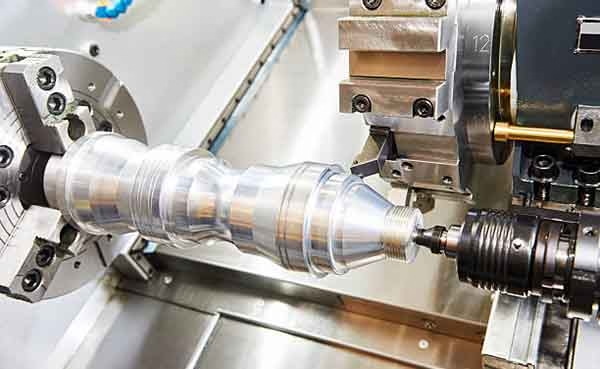
Start From the Part, Not the Machine
Each technique below solves a specific geometry or cost problem. The order follows the decision path we use when a drawing arrives.
Simultaneous 5-Axis Machining: When All Five Axes Move at Once
In simultaneous 5-axis machining the tool tip is continuously repositioned while the two rotary axes turn. The cutter can lean into a wall, roll along a compound surface and keep the same contact point instead of lifting and resetting. That continuous motion is what buys you access to undercuts, deep pockets with curved floors and blended surfaces that a vertical cutter cannot reach.
The gain is not only geometric. One setup replaces three or four, so datum error stops stacking up between operations. On a part with five angled faces and two bores on different axes, a single 5-axis cycle usually holds true position better than a sequence of 3-axis setups, simply because the part never leaves the vise.
The cost side is real too. Programming takes longer, the CAM engineer has to control lead and tilt angles to avoid holder collision, and cycle time can run higher than indexed work on simple shapes. We run 16 simultaneous 5-axis machining centers at GreatLight for exactly this reason: the parts that need them rarely have a cheaper alternative.
Typical fits include impellers, turbine blades, medical bone plates, optical housings and any surface where the tool axis must follow a curve. If your part is a plate with holes on one face, this technique is the wrong tool.
3+2 Positioning: Index the Rotary Axes, Then Cut in Three
3+2 positioning, sometimes called 5-axis indexing, locks both rotary axes at a fixed angle and then machines with ordinary 3-axis interpolation. The tool stays normal to the face being cut. You get access to compound angles and undercuts without any of the dynamic control that simultaneous motion demands.
Programming is the main reason shops default to it. A 3+2 toolpath behaves like a 3-axis toolpath, so feeds, speeds and stepover follow the same rules your team already knows. CAM setup time drops, post-processor risk drops, and the machine can use its full rapid and feed rates because no rotary axis is moving mid-cut.
Rigidity is the second gain. With the rotary axes clamped, the cutting load path is short and predictable. We see this on stainless and tool steel jobs where a locked trunnion holds better surface finish than a continuously tilting table. Cycle times on medium-complexity parts often land 20 to 40 percent below a full simultaneous approach.
The limit is reach. A single 3+2 orientation can only cut what the tool can see from that angle, so deep cavities or wrapped features may need two or three indexed positions. That is still cheaper than four 3-axis setups, but it is not the same as full continuous motion.
Choosing Between Simultaneous 5-Axis and 3+2
Use this when the drawing has angled features and you are deciding which strategy to quote.
| Factor | Simultaneous 5-axis | 3+2 indexing |
|---|---|---|
| Tool axis during cut | Moving continuously | Locked at one angle |
| Best geometry | Sculpted, wrapped, blended surfaces | Angled faces, undercuts, deep pockets |
| CAM effort | High, needs tilt and lead control | Low, standard 3-axis logic |
| Setup count | Usually one | One to three |
| Rigidity at the cut | Lower, rotary axes in motion | Higher, axes clamped |
| Surface finish on walls | Even on compound curves | Even on flat and angled faces |
| Typical use | Impellers, blades, optical parts | Housings, brackets, manifolds |
High-Speed Machining and Trochoidal Milling for Deep Pockets
High-speed machining is not just a higher spindle number. The point is constant chip load: the CAM path keeps radial engagement fixed while axial depth grows, so the cutter removes more material per pass without spiking the cutting force. Heat leaves with the chip instead of soaking into the part.
Adaptive roughing is the usual way to get there. Radial engagement is held low, often 5 to 15 percent of tool diameter, while axial depth can run one to three times the diameter. On 7075 aluminium and Ti-6Al-4V this keeps deflection small and lets a smaller tool clear a cavity that would stall a larger one.
Trochoidal milling is the extreme version of the same idea. The tool travels in a looping path with a controlled arc of engagement, cutting a slot wider than itself. Chips clear better, the tool body stays cooler, and deep slots in 17-4PH or 4140 come out with less taper and fewer tool changes.
Both techniques need a rigid platform and a CAM programmer who understands the material. Applied to a thin-walled part with no support, the same paths can chatter. We check wall thickness before committing to an adaptive strategy.
Tombstone Fixturing to Keep the Spindle Cutting
Every minute a machine sits idle while an operator loads a part is a minute the spindle earns nothing. Tombstone fixturing attacks that directly: several parts are clamped to the faces of a cube or angle plate, and the rotary table indexes from face to face. The operator loads one face while the machine cuts another.
The math is simple. A tombstone with four faces and three parts per face gives twelve parts per cycle. Even at a modest cycle time, the load and unload window disappears from the runtime because it happens during cutting. On aluminium brackets and stainless connectors we regularly see effective machine utilization move from the low sixties into the eighties.
Fixturing cost is the trade-off. Each tombstone needs its own soft jaws, clamps or vacuum plate, and that tooling has to be built before the first part is cut. For a 50-piece order it rarely pays back. For a repeat order that runs monthly, it usually does within the first two or three cycles.
Designers can help here. A part that shares a common mounting feature with its siblings can be clamped with one fixture family, which spreads tooling cost across the whole order instead of one part number.
In-Process Probing and Toolpath Synchronization
Probing closes the loop between what the machine assumes and what is actually on the table. A spindle-mounted touch probe measures a datum, a bore or a machined face, and the control shifts the work offset before the next operation runs. On castings and forgings with variable stock, this removes the need to dial in every part by hand.
The same probe can check a critical dimension mid-cycle. If a bore is trending toward the low limit, the control adjusts the finishing pass. That is how a shop holds ±0.005 mm on a production run without inspecting every part offline. We still run 100 percent inspection before shipment, but probing keeps the process from drifting in the first place.
Toolpath synchronization is the quiet one. On a mill-turn or a 5-axis cycle with two rotary axes, the rotary motion and the linear motion have to finish their moves together. If the rotary axis lags, the cutter leaves a witness mark or a facet on the surface. The fix lives in the CAM settings: rotary feed limits, smoothing tolerances and lead-in geometry.
This is where hidden cost accumulates. A part that machines in 40 minutes on paper can take 55 on the floor because the control is throttling rotary moves. Reviewing those parameters before the first cut is cheaper than reworking a batch.
Questions Engineers Ask Before Choosing a Strategy
How do I know if my part needs simultaneous 5-axis or 3+2?
Look at the surfaces, not the part name. If every feature can be reached from one of two or three fixed tool angles, 3+2 will be cheaper to program and usually faster to cut.
Simultaneous motion earns its cost when the tool axis has to follow a curve, when surfaces blend across multiple faces, or when a single setup is the only way to hold the tolerance. Send us the STEP file and we will tell you which one we would quote.
What tolerance can you actually hold on multi-axis work?
We work to ±0.005 mm (±0.0002 in) on critical features, with surface finish from Ra 0.2–0.8 μm on fine finishing work up to Ra 1.6–3.2 μm as machined.
The achievable number depends on geometry and material. A short bore in aluminium is easier than a long unsupported wall in titanium. The DFM report we return with the quote flags the features that will be tight.
Does high-speed machining work on titanium and tool steel?
Yes, and that is where it matters most. Adaptive paths with low radial engagement keep heat in the chip rather than the workpiece, which limits work hardening on Ti-6Al-4V and reduces tool wear on tool steel.
The requirement is a rigid machine and a CAM programmer who will tune the parameters to the material. Running an adaptive path at the wrong chip load is worse than conventional roughing.
When does tombstone fixturing pay for itself?
Repeating orders. If a part number runs once, the tooling cost rarely justifies it. If it comes back monthly or quarterly, the reduction in load and unload time usually recovers the tooling within two or three cycles.
We also use tombstones to group similar parts from the same family, which spreads fixture cost across several part numbers.
Can you work from a 3D model only, without a drawing?
Yes. STEP and IGES files are enough to program and quote. A drawing helps when there are datums, fits or callouts that the model does not carry, such as thread class or specific surface finish.
Uploads are secure and confidential, and we can sign an NDA before files are transferred if your project needs it.
What lead time should I plan for on a multi-axis part?
Quotation and DFM analysis come back within 12 hours, and production can start within 24 hours of approval. Most parts ship in 3 to 5 days.
Complex 5-axis work with custom fixturing may need longer for the first article. We will state that in the quote rather than after the order.
Send the Drawing, Get a Strategy Back
Upload your model and we will return a quote and DFM analysis within 12 hours, including which of these seven techniques we would use and why.
Quotation in 12 hours±0.005 mm toleranceNo minimum order quantityNDA on request









