Understanding how a part design behaves under stress is important for industrial designers, engineers or Essential for anyone working in 3D printing. In fact, technical simulation software has evolved. It becomes easier to use and moves beyond highly specialized applications to consumer product design and development, enabling more people to save time, reduce costs and innovate.
When designing functional parts, destructive testing prototype after prototype wastes a lot of time, material and money. Of course, some field testing is necessary, but today’s software simulations can significantly reduce the time spent redesigning parts. This is ideal when working under tight deadlines or even as a side project.

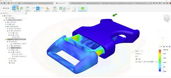
Autodesk Fusion simulation tools help you find and fix weak links in your design (Source: Autodesk)
Knowing that you need to rethink as soon as possible and understanding the mechanics (or mechanical issues) behind the design can make you a better designer. The ability to understand the mechanical properties of a design before production is very powerful, especially in additive manufacturing where materials that have never been used before are often used to construct unique parts that have never before been used. been manufactured previously.
Let’s take a look at the best simulation tools and practices that can help you move more intelligently from idea to final part.
Simulation software

Ansys Discovery simulation software (Source: Ansys)
Virtual stress testing allows you to evaluate how fit-for-purpose your current design is and where improvements can be made. Understanding the mechanics of a design will allow you to understand what design features can change the behavior of stresses in specific areas of a part. This comes into play when you design for manufacturing, that is, when you realize how the design will be made (injection molding,3D printing, CNC machining, etc.) or if it can be produced.
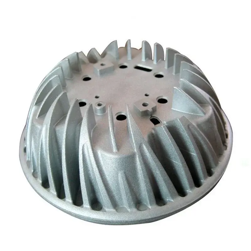
For example, perhaps the filler material you chose to reduce the weight of the bracket is preventing it from doing its job, or the radiator assembly you redesigned to combine parts into a complex shape may not work as expected. These problems can be discovered and corrected using simulation software.
New software tool directly addresses simulation issues 3D printing problems, while other software tools have been extended to incorporate additive manufacturing design principles.
But which practice tests can provide the necessary information? Below, we look at the most popular and affordable computer-aided engineering software tools. Fusion 360’s simulation tools (known today as Fusion) serve as an example of how these programs typically work.
We will show you how to use Fusion Application Mock Test. We’ll then look at some of the differences between simulation analysis and other industrial software such as Ansys, Creo Simulate, NX, and Abaqus, as well as the more powerful simulation environments they offer. We’ll also cover process simulation software, which are products that simulate the 3D printing process itself, allowing you to predict and correct manufacturing failures such as warping and twisting before they occur. produced in the manufacturing chamber.
But wait, you need to understand some mechanical engineering concepts first (if you haven’t already)——The most important thing is: finite element analysis (FEA).
What is finite element analysis?

Simulated construction and real construction (Source:Ansys additive solutions)
FEA studies how a part or assembly interacts with its environment, whether it’s the heat and pressure in an engine or the cold and weightlessness of space. It takes into account the mechanical and material constraints of the part and applies them to digital simulations. The overall goal is to understand how the part behaves under specific stresses and strains.
In more technical terms,FEA is the use of a numerical mathematical technique called finite element method (FEM) to simulate a given physical phenomenon. Don’t worry, the software will mostly do the math for you.
As we have already mentioned, simulation saves time in building prototypes and running experiments, money on materials to build prototypes and test benches to test the prototypes, and external help such as mechanics for more iterations.
In the additive manufacturing industry, use FEA is the key to saving development time and costs. But there is more. Other benefits of integrating FEA into your additive manufacturing workflow include:
Better understand material selection and options
Better understand the appropriate test scenarios to accurately stress your parts
although FEA has enormous benefits, but it does not eliminate the need for physical testing. It still remains to be tested. There is a difference between running simulations (FEA) on a computer and testing on test equipment in real-world scenarios. But simulation can often prevent you from doing bad physical tests, following a completely wrong design, and building with inappropriate materials.

Constraint simulation in Fusion 360 (Source: Autodesk)
when you continue to use When you use FEA and FEA software tools, you will better understand how many force-specific applications are required and how this determines the success or failure of the analysis. For those new to the process, feel free to run several simulations until the results make sense.
From there, you can modify your design accordingly, prototype it, and then test it in real-world scenarios. Compare your analysis with accurate lifetime test results to improve the setup and parameters of your physical tests or simulation, or both.
FEA software or computer-aided engineering (CAE)/computer-aided design (CAD) software with FEA tools is often complex and must be run on hardware capable of running simulations without getting bogged down. Later in this article, I will introduce software packages that can be used to run finite element analysis on 3D printed parts along with their system requirements, which are worth noting.

Fusion 360 simulation options (Source: Autodesk)
Define the scope of the simulation
Before you start using Before FEA, you also need to know something about FEA. Mainly, although the software simulates pressure, you still need to tell it how to simulate pressure and what pressure to simulate.
There are several types of simulations available in FEA/CAE software packages.
static analysisStudy the deformation of parts under stress and deformation. This is one of the most common types of structural analysis.
dynamic analysisIntroduce noise, vibration and acceleration into the mix.
Multibody dynamics, for its part, involves constraints on multidimensional and complex assemblies comprising several moving parts (such as an engine). The main goal is to understand not one but several forces operating within the system and how these external factors affect each part.
There are a few things to keep in mind as you begin to analyze your setup. Depending on your application, there may be an industry standard you can consult. This makes configuration easier for you. Typically, these criteria include boundary conditions and initial parameters, depending on your application. Sometimes initial parameters are used to define the study, such as applied forces, material properties, angle of attack, pressure, direction, etc.
Another important term, factor of safety, refers to the ratio of a part’s strength to its maximum stress. Make sure you set up your study correctly using appropriate boundary conditions and assumptions.
Running a simulation should include the following steps:
to use CAD software for modeling parts or assemblies
Generate a mesh model
Identify relevant industry standards or boundary conditions (if applicable)
Run a simulation
Post-processing and analysis. Draw conclusions and refine the mesh if necessary or redesign the part and rerun the simulation.
Remember, run FEA simulation is not a one-size-fits-all process. This is an iterative process that involves testing initial parameters and initial designs. Then you take the results, analyze them, improve the design and retest. Rinse and repeat until the results meet the success criteria you outlined at the start of the study. If no design changes are required, you have a functional design that you are confident will provide acceptable performance.
Merger simulation

Event simulation in Fusion 360 predicts the effects of drops and impacts (Source: Autodesk)
Now you know FEA, let’s discuss the features Autodesk offers in Fusion and as optional simulation extensions.
Fusion’s base subscription includes simulation tools including:
static constraint
Model frequency
thermal analysis
heat stress
structural buckling
nonlinear static constraint
event simulation
Shape optimization
Static constraints will allow you to determine the maximum constraints and displacements of your model or component. Modal frequencies come into play when it comes to system vibrations. Thermal analysis is responsible for the distribution of heat and its effect on the room. Buckling is designed to understand what is happening or how a part fails under compression. Understanding nonlinear constraints allows you to use nonlinear materials in assemblies to analyze permanent deformation. Event simulation introduces temporal dependencies into the model, which is useful for real-time simulations.
Most of my experience in finite element analysis comes from nonlinear stress analysis and event simulation. The discussion focuses on shape optimization, showing how components can be made lightweight or stiff to ensure cost-effective and sustainable production.
I use Fusion’s FEA software improved the design of a camera mount for one of my clients. I run a product development company where my mission is to improve client designs and ensure the designs meet their requirements. Thanks to FEA, I was able to determine:
What is the best design for a medium to be used in its environment
What forces are exerted on the part over time?
Additional reductions and modifications to maintain installation rigidity
Since the mount is subject to high g-forces (drift, abrupt changes in acceleration), I ran event simulations to understand the lifespan of the parts and how to further refine the design. While Autodesk is constantly improving its software with frequent updates and I decided to use Fusion 360’s FEA software. Fusion is also relatively affordable for small startups.
Not to mention,Fusion includes a very handy toolbox for additive manufacturing and generative design, and I like having my workflow bundled into one package where I can design, refine, analyze, and manufacture.
Of course, if you want For more complex simulations within the Autodesk ecosystem, Fusion Simulation Extension ($1,465/year) is available. This extension offers more powerful simulation tools, including:
Nonlinear static stress: behavior in large deformations, movements, contacts and load changes)
structural buckling
Event simulation: predicting the evolution of forces over time 3D design performance.
Modal frequencies: check how free, natural vibrations affect you
Injection molding
Electronic Cooling: Identify the risk of failure of electronic components and parts due to overheating
Generative design: Explore multiple outcomes that meet your design specifications while reducing weight and improving performance.
Thermal simulation: trace heat transfer and temperature-induced stress
Injection molding simulation for comparison Particularly useful is the performance of 3D printed parts compared to identical injection molded parts.
Autodesk also offers an additive manufacturing simulation tool as part of the Additive Build Extension for Fusion, but this is not an FEA tool, but allows you to reproduce real additive manufacturing processes (selective laser sintering , powder bed fusion, etc.) and predict common print distortions and failures. Based on the simulation results, Fusion can automatically compensate the geometry to achieve the desired shape when 3D printing. A more advanced version of this feature is available through Autodesk’s Netfabb software.
However, for those less tech savvy,Fusion Core FEA is a great tool to start with. It uses a “lite” version of Autodesk Nastran, which makes the software user-friendly. Check out this handy tutorial on setting up simulations in Fusion.
Of course, there are more powerful simulation programs. Some of the products we mention below are not only capable of simulating almost any stress or event, but they can also help you redesign your rooms for the better. These solutions also incorporate multiple levels of simulation at every stage of the product lifecycle, from concept to print to quality assurance, to create a complete closed loop.
Best simulation software

The packages below allow for deeper nonlinear simulations, multiphysics, mesh fine-tuning, and the ability to use different elements. Some can not only run various simulation scenarios but also suggest optimal design directions.
Another sophisticated feature you can find in some simulation applications that goes well beyond what we’ve covered here is digital twins, which are complete virtual prototypes of real-world systems.
1、Ansys Discovery Simulation 2024 R1

perhaps the deepest One of the CAE packages comes from software company Ansys. Ansys Discovery does not start with design and then refine it through simulation like Fusion, but it is a simulation-based 3D design tool. Providing technical depth to each analysis is the strength of the program. Not to mention the level of refinement and customization brought to each simulation. It is used to simulate mechanical design, optics, fluids, surgical implants, etc.
Ansys offers a variety of software packages, including Ansys Mechanical (a versatile, easy-to-use tool), Ansys Fluent (for advanced physics modeling), and Ansys LS-Dyna (for nonlinear simulation, multiphysics and more). They also offer a free trial, limited to a certain number of nodes it can solve, but it’s worth a try.
Ansys also includes an additive suite (additive, such as additive manufacturing or 3D printing) which includes:
Additive preparation
Additive printing
Additive science
2、Dassault Systèmes Simulia 2024

Dassault Systèmes Abaqus finite element analysis in Simulia software (Source: Dassault Systèmes)
Simulia from Dassault Systèmes (maker of Solidworks) is a powerful tool that accelerates the process of evaluating the performance, reliability and safety of materials and products before creating physical prototypes.
It offers a wide range of simulation types such as multiphysics, computational fluid dynamics, standard mechanical static analysis, etc. This is an interesting solution for engineers in the automotive industry, who need to simulate many different effects, from vehicle loads and vibrations to collisions and acoustic-structure coupling.
Abaqus Unified FEA is an optional product suite for Simulia. It has three modules (standard, explicit and multiphysics) to handle common and complex engineering problems covering a wide range of industrial applications.
3、Comsol Multiphysics 6.2

Not intended for beginners, Comsol Multiphysics software can be used by engineers and researchers to simulate real-world designs, equipment and processes across all industries. Common uses include battery design and product design of fuel cells, semiconductor devices, microfluidics, and components with chemical reaction characteristics.
This is another multi-module solution designed to cover all the bases of engineering simulation, from fluids and thermals to chemistry and sound, allowing you to select only the modules you need. The update to version 6.2 brings faster calculations and an improved user experience, and the latest version now uses a new agent model framework that enables more accurate digital twins.
Fortunately, for those with less experience, it is compatible with a long list of CAD program integration including Revit, AutoCAD, Solidworks, Solid Edge, etc. For example, integrating Comsol Multiphysics with LiveLink for Solid Edge can help you optimize your design through simulation while providing simultaneous updates to your design during simulation. Bidirectional updates are automatic when both programs are open simultaneously and you solve an optimization study or run a parameter sweep. This integration is not the same as switching between two different programs.
4. Siemens Solid Edge and NX 2024

For most product designers, the entry point into the powerful world of Siemens software is Solid Works CAD tool, which integrates finite element analysis (FEA).
Based on finite element modeling and Simcenter Nastran FEA technology, Solid Edge Simulation offers a comprehensive motion simulation suite that allows you to evaluate and visualize the interaction of parts in an assembly, understand the performance of your product throughout its operating cycle and its functions in the real world.
Siemens is present Nastran was developed for NASA in the 1960s. It provides multidisciplinary structural analysis, nonlinear analysis, integrated fatigue and vibrational fatigue analysis. The new automated mesh generation process in Solid Edge Simulation makes mesh generation easier and can be controlled without parameters.
The company said that in the latest update,Improvements in Solid Edge 2024 focus on improving user experience. Thanks to artificial intelligence and the cloud, visualization is now faster and additional products are available on demand.
FEA in Solid Edge is a powerful tool, but advanced industrial designers will choose the most advanced and comprehensive simulation environments from Siemens NX and Simcenter 3D.
5、Altair Inspire Print3D

when it comes to It’s hard to know where to start when it comes to Altair’s simulation solutions. If simulation is possible, Altair has the tools. Almost all sectors of engineers, designers and researchers are covered by Altair.
We will therefore focus here only on 3D printing and DfAM functionality.
existIn the “Industrial Design” category, Altair offers topology design, visualization and optimization tools, while in the “Manufacturability” category you can find all their simulation tools. There are modules to assess product feasibility, optimize manufacturing processes, and conduct virtual trials of many conventional, subtractive, and additive manufacturing processes for comparison purposes.
Altair’s product manufacturability applications are suitable for multiple industries, including automotive, aerospace, electronics, pharmaceutical and heavy industry. In fact, there are about two dozen simulation programs, including Inspire Print3D, which is specifically designed to create structurally efficient 3D printed parts using selective laser melting (SLM).
Daguang focuses on providing solutions such as precision CNC machining services (3-axis, 4-axis, 5-axis machining), CNC milling, 3D printing and rapid prototyping services.