
01
You re-chuck the part four times
Every extra setup adds a datum shift. Bolt patterns that should sit 0.01 mm apart land 0.05 mm out, and the actuator flange will not seat without reaming holes on site.
Joint housings, wrist links and brackets cut from aluminum and titanium in one setup. We hold ±0.005 mm across five faces so actuators, bearings and encoders drop in without hand fitting.
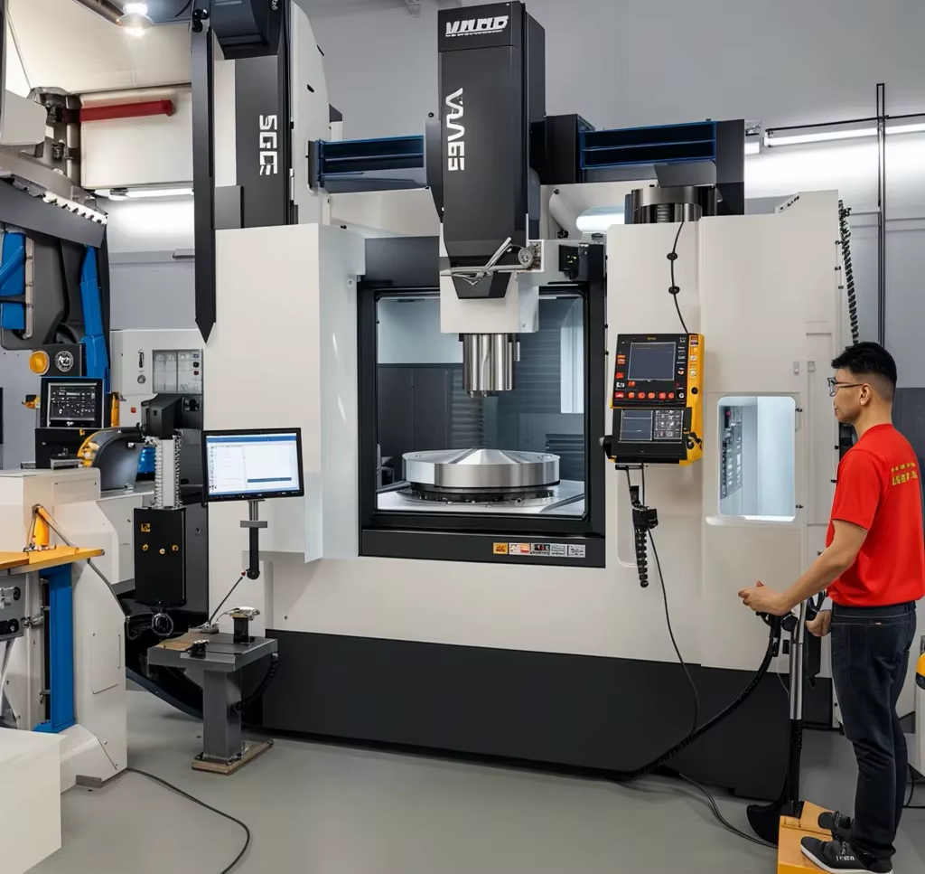
Most of these trace back to how the part was set up, not to the drawing.
Every extra setup adds a datum shift. Bolt patterns that should sit 0.01 mm apart land 0.05 mm out, and the actuator flange will not seat without reaming holes on site.
Thin walls relax when the clamps come off. A bore that measured round on the machine reads 0.02 mm out of round after anodizing, so the bearing either rattles or will not slide in.
Housing faces that are not square to the axis tilt the encoder disc. The arm hunts at low speed, and tuning the loop cannot fix a geometry error. Flatness and perpendicularity have to be cut in.
Oversized bosses and thick flanges add mass at the wrist, so the motor works harder and cycle time slips. Designers need wall sections near 1.5 mm kept stable, not solid blocks.
The joint is only as good as the surfaces that reference each other.
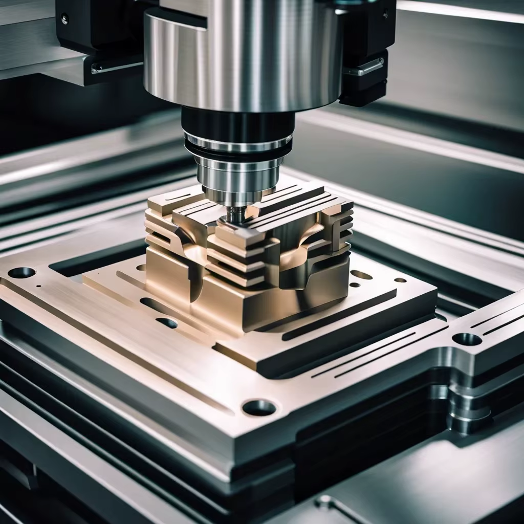
A robot joint has features on every side: a motor mount, a bearing bore, a cross-roller seat, cable passages, mounting ears. On a three-axis machine that means four or five setups and a fresh datum each time. On our simultaneous five-axis centers the part stays in one fixture, so the bore and the bolt circle keep their relationship through the whole cycle.
We plan the setup from the datum scheme, not from what is easy to clamp. If your drawing calls out the bearing bore as datum A and the flange face as datum B, those two surfaces come off the same spindle in the same operation. Everything else is measured against them.
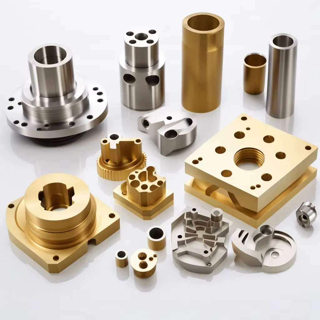
Joint housings are thin by design. Weight at the wrist costs torque, so walls run 1.5 mm to 3 mm and the bore sits close to the outside skin. Clamp pressure deforms that wall while cutting, and the part springs back after the vise opens.
We rough with extra stock, let the part cool, then finish with light radial passes and low clamping force. Bores are checked for roundness and taper, not just diameter. When anodizing or hardcoat comes after machining, we mask and re-check the critical bore, because a coating can move a tight fit by more than the tolerance you allowed.
Not every joint component needs five axes. This is how we split the work.
| Part type | Best process | Why |
|---|---|---|
| Joint housing, 3+ faces | 5-axis, one setup | Datum stack stays closed |
| Wrist link, long and slim | 5-axis with tailstock | Deflection controlled along length |
| Cross-roller bearing seat | 5-axis, finish in place | Roundness and squareness together |
| Simple end cap, one face | 3-axis mill | Five axes add cost, not accuracy |
| Turned shaft with cross holes | Mill-turn center | Turning and milling in one cycle |
| Prototype bracket, 1-5 pcs | 5-axis, no tooling | Design changes absorbed in CAM |
Six capabilities that cover a robot joint from raw stock to coated part.
Simultaneous five-axis milling for joint housings, wrists and brackets. 16 centers, up to 4,000 mm of travel.
For single-face plates and covers where five axes would only add cycle time.
Mill-turn centers handle turned shafts with cross holes and flats in one cycle.
One-off joints for fit checks and kinematics tests before the design freezes.
Anodizing, hardcoat, electroless nickel, bead blasting and laser marking.
100% inspection before shipment, with dimensional reports on request.
Numbers below are what our process holds in normal production.
| Item | Range | Notes |
|---|---|---|
| Tolerance | ±0.005 mm | ±0.0002 in on critical fits |
| Surface finish | Ra 0.2–0.8 μm | Ra 0.8–1.6 μm standard |
| Aluminum | 6061, 7075, 2024, 6082 | Lightweight joint bodies |
| Titanium | TC4 (Ti-6Al-4V), TA2 | High-load wrist links |
| Stainless | 303, 304, 316L, 17-4PH | Pin seats and inserts |
| Max part size | 4,000 mm | Across the long axis |
| Anodizing | Clear, color, hardcoat | Hardcoat adds 20–30 μm |
| Laser marking | 1.5 mm min height | Part numbers and traceability |
Founded in 2011, three wholly-owned plants, 150 technicians.
Fifteen years of production work in Dongguan, next to Shenzhen, plus a factory in Singapore.
16 five-axis, 12 four-axis, 27 three-axis, 16 mill-turn centers and the support equipment around them.
Not a lab number. It is what the process repeats on joint bores and flange faces.
Raw material check, in-process monitoring, final inspection before anything ships.
We return a quotation with a free DFM review within 12 hours. Production can start in 24 hours.
ISO 9001:2015, IATF 16949:2016, ISO 13485:2016 and ISO 27001:2022.
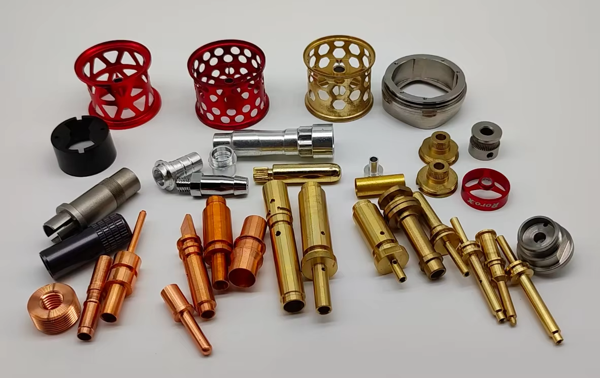
Bore and bolt circle cut in the same operation so the motor flange seats without shimming.
Thin-wall sections held stable through roughing, finishing and anodizing.
One-off and small-batch joints for kinematic testing before tooling is cut.
We plan the fixture from your GD&T before the first tool touches the stock.
If the part has features that reference each other on three or more faces, five axes pay for themselves. A joint housing with a motor mount, a bearing bore and cable exits is the classic case.
If your part is a flat cover with holes on one face, a three-axis machine does it cheaper and just as accurately. We will tell you which one your drawing needs.
Rough machining leaves stock, the part cools, then finishing takes light radial passes with low clamp force. Bores are measured for roundness and taper, not only diameter.
When hardcoat or anodizing follows, critical fits are masked and re-checked, because coating thickness can eat a tight tolerance.
6061-T6 covers most housings and brackets. It machines cleanly, anodizes well and keeps cost down.
7075 gives higher strength for wrist links that carry bending load, but it costs more and is harder to weld. 2024 sits between the two and is common in aerospace-style joints.
Yes. TC4 (Ti-6Al-4V) and TA2 are used for high-load links, and 17-4PH, 316L and 303 for pin seats, inserts and bushings.
Titanium needs slower cutting speeds and more tool changes. Expect a longer cycle than the same part in aluminum, and plan for it in the schedule.
No. We run from a single prototype to 10,000+ part runs. Prototype joints are common before the kinematic design is frozen.
The first article and the production run use the same CAM and fixtures where possible, so what you test is what you get in volume.
Quotation and a free DFM analysis come back within 12 hours of a complete drawing and model. Production can start within 24 hours after approval.
Parts normally ship in 3–5 days depending on quantity, finishing and material availability.
Every part is inspected before shipment: raw material check, in-process monitoring and final inspection. Dimensional reports are available on request.
We work to ISO 9001:2015, with IATF 16949:2016, ISO 13485:2016 and ISO 27001:2022 also held.
Uploads are secure and confidential. We can sign an NDA before you send drawings, and the NDA page is on the site.
Files are not shared outside the project team, and customer models are not used as samples or marketing material.
Upload the STEP file and drawing. An engineer reviews the datums, the wall sections and the finishing before we quote.
12-hour quote100% inspectionNo minimum orderNDA on request
Trusted by engineers and manufacturers worldwide










Upload your 3D model or 2D drawing and get a quotation with a free DFM analysis. Maximum processing size 4,000 mm.
CNC Metals 13 grades
CNC Plastics 10 grades
Machines & processes 12 options
Surface & post-processing 10 options
Material: not selected Machine: not selected Post-process: not selected