GreatLight CNC Machining Factory logo
CNC Machining
Rapid Prototyping
Materials
Industries
News
About GL

Get Instant Quote

GreatLight · Robotics Components

Robot Arm Joints CNC Machining

Harmonic-drive housings, joint brackets, link arms and motor mounts machined on sixteen five-axis centers, so load-carrying bores and mounting faces come off one setup instead of three.

±0.005 mm on bores16 five-axis centers7075 · 6061 · Ti-6Al-4VNo minimum order
Robot arm joint housings and link parts machined on five axis CNC centers
±0.005 mmBore and seat tolerance
Ra 0.2–0.8 μmBearing seat finish
16Five-axis centers
12 hoursQuotation with DFM notes
Failure modes

Four ways a joint loses position without ever being out of tolerance

A joint that measures correctly on the bench can still run rough under load. The causes below are the ones we meet most often when a customer brings us a redesign.

01

Two bores in tolerance, yet offset from each other

Each bore can sit inside its own limit and the pair still misses coaxiality. The bearing then sits cocked, preload becomes uneven, and one side of the joint runs hot. Machining both bores from one datum is the direct fix.

02

Does your seat average to size but still preload the bearing?

Diameter alone does not describe a bearing seat. A three-lobed bore that averages to nominal will pinch the outer race. We check form on seats rather than only size, and we say so when the drawing is silent about it.

03

Bolted down, the housing pulls out of square

A flange that is not square to the bore is flat on the surface plate and wrong in the assembly. When the bolts are tightened the housing is pulled, and the axis tilts with it.

04

Has the arm lost position after a few months of service?

Twisted links and drifted bores show up as position error at the tool centre point, not as a failed part. By then the joint has been rebuilt twice and the servo has been compensating for geometry.

How we hold a joint together

Three things that decide whether a joint runs smoothly

The geometry of a robot joint is simple. What decides whether it lasts is how the bores relate to each other and what the bearing seats actually measure.

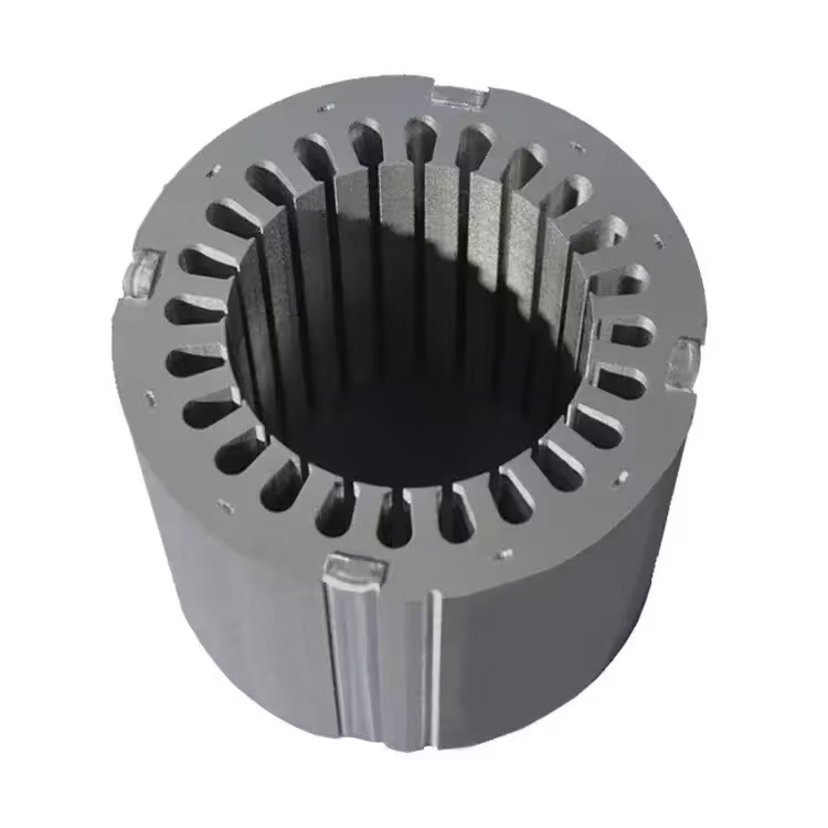
Precision machined stator and rotor components for robot and drive assemblies
Bore alignment

Both bores cut from one datum, not two operations

This is the main reason joint work comes to five-axis centers. The bracket is held once and the rotary axes bring each bore to the tool, so both bores share a datum and a spindle axis. Where a bracket is too large for the rotary table, we machine a reference face first and use it for every later operation.

The same logic applies to the output flange and the motor pilot. Cut them in the setup that cuts the bore and the relationship between them is machine-made, not fixture-made.

  • 1
    One setup per load pathEvery face that carries or locates a bearing comes off the same setup, so the stack never accumulates across operations.
  • 2
    Reference face for oversized partsWhen a part cannot be turned on the table, a machined reference face carries the datum through the remaining operations.
  • 3
    Verified before releaseCoaxiality and squareness are measured on the finished part, with results reported on request.

Get Instant Quote

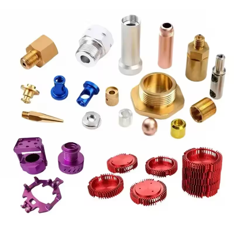
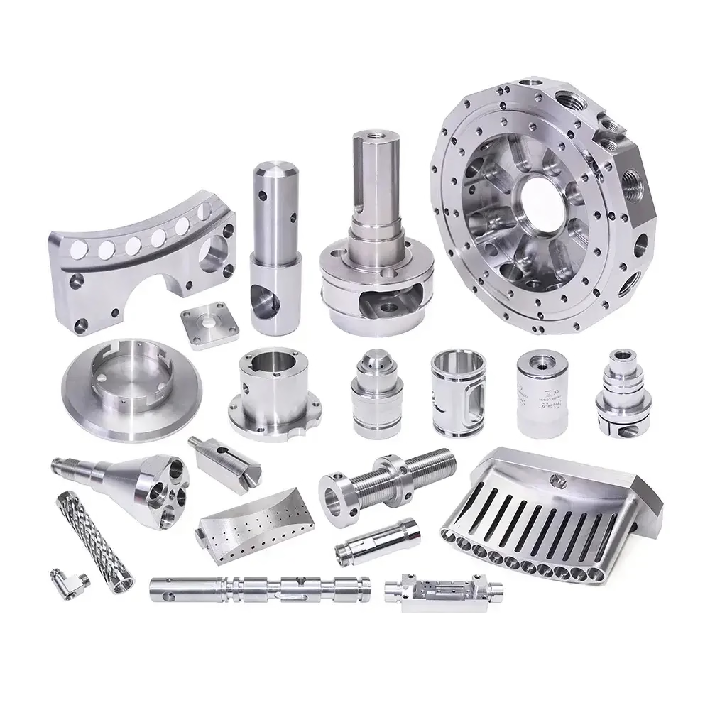
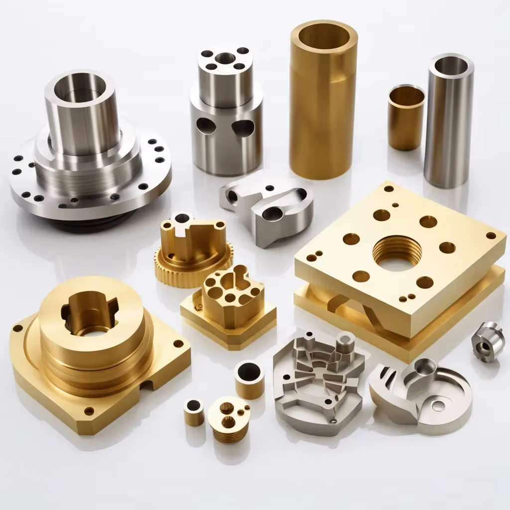
High-precision machined parts checked for form before shipment
Form and finish

Roundness and seat finish checked, not assumed

A bearing seat is a system of diameter, roundness, taper and surface finish. Two of those are on most drawings; the other two decide whether the joint feels tight at speed.

Seats that carry a pressed or preloaded bearing are finished to Ra 0.2–0.8 μm and checked for form, because a lobed or tapered seat can be exactly on diameter and still load the race unevenly.

  • 1
    Form measured, not only sizeRoundness is verified where a bearing is pressed or preloaded, rather than inferred from a caliper reading.
  • 2
    Finish matched to the applicationRa 0.2–0.8 μm for bearing and sliding seats, Ra 0.8–1.6 μm for mating faces and seals.
  • 3
    Thin-wall parts allowed to settleRough with stock left on, then finish in light passes after the last clamp change, so the wall is measured in its released state.

Talk to an Engineer

Titanium joint components machined on five axis centers
Material and weight

7075, 6061 or titanium, decided by the load path

For most arm joints the material question is a stiffness question. 7075 gives the highest stiffness for a given section, which lets you thin the walls and still hold position under load. 6061 costs less and machines faster, and it is the right default where stiffness is not the limiting factor.

Titanium enters when the load concentrates at a small joint and steel inserts are not acceptable. It cuts far more slowly, so the design has to justify it, usually by removing a part rather than by making one part stronger.

  • 1
    7075-T6 and 6061-T6The two workhorses: 7075 where stiffness governs, 6061 where corrosion resistance and cost do.
  • 2
    TC4 (Ti-6Al-4V)For small joints carrying concentrated loads, cut with short rigid tools on five-axis centers.
  • 3
    17-4PH and 4340Shafts, pins and inserts where the load path has to run through steel.

Talk to an Engineer

Component map

What we machine for a robot joint, and what has to be tight on each

Every component below is quoted against one question: which feature decides how the joint behaves in service?

ComponentCritical featureWhy it decides how the joint feels
Harmonic-drive housingInner bore and its concentricity with the output flangeAny eccentricity becomes a once-per-revolution ripple in the output motion
Joint bracket or yokeBore alignment between the two arms and squareness to the mounting baseOffset bores tilt the axis, and the servo compensates for it all day
Link armParallel faces and end boresBent or twisted links show up as position error at the tool centre point
Motor mountPilot bore concentric with the bolt circleA pilot that is off centre shifts the rotor and loads one bearing harder
Cable guide and coverWall thickness and running clearanceThin covers rub through where clearance was assumed rather than measured
What we machine

Joint components we run on five-axis centers

Part families that arrive with a robot joint project, from a single prototype to a production set.

HD

Harmonic-drive housings

Thin-wall housings with an internal bore, a flange and a bolt pattern that all have to agree with each other.

YOKE

Joint brackets and yokes

Two-arm brackets where bore alignment decides the preload, machined in one setup or against a machined reference face.

ARM

Link arms and segments

Long parts where parallel faces, end bores and weight relief have to be produced without inducing twist.

MTR

Motor mounts and adapters

Pilot bores, bolt circles and mounting faces made concentric in one operation instead of three.

PIN

Pins, dowels and inserts

Steel load-path parts in 17-4PH, 4340 or hardened grades, turned and milled to the fit you specify.

SET

Prototype and small-batch joint sets

A complete joint set quoted as one order, so the parts are machined to the same revision and arrive together.

Tolerance plan

What we hold, and what it is checked on

What we holdWhere it appliesHow it is verified
±0.005 mm / ±0.0002 inBores, seats and faces called out on the drawingMeasured on the finished part, with results reported on request
Ra 0.2–0.8 μmBearing and sliding seatsCompared against the surface callout on the drawing
Ra 0.8–1.6 μmMating faces and sealsChecked where the seal or gasket type makes finish critical
Roundness and taper on seatsAny bore carrying a pressed or preloaded bearingForm measured, not inferred from a diameter reading
One datum per partRelated features cut in the same setupReported as a feature-to-feature relationship rather than separate dimensions
Why GreatLight

What a robotics project gets from us

Joint work is judged in service, not on the delivery note. These are the numbers we work to and the checks behind them.

±0.005

Millimetres on bores and seats

Our stated machining tolerance, held on the features you call out and on the dimensions the drawing leaves open, with ±0.0002 in as the imperial equivalent.

Ra 0.2

Micrometre finish on bearing seats

Fine finishing reaches Ra 0.2–0.8 μm, which is what a pressed or preloaded bearing needs from its housing.

16

Five-axis centers

Enough capacity to hold a joint set in one setup rather than splitting it across machines and datums.

13485

ISO 13485 for medical hardware

Medical and laboratory robotics run under the same quality system as our medical device work, alongside ISO 9001:2015.

1

Datum per part

Related features are cut in one setup, so the relationship between a bore and its flange is decided by the machine, not by a fixture.

0

Minimum order quantity

One joint is a normal order and runs on the same equipment as a production set, with the same inspection.

±0.005 mmBore and seat tolerance
Ra 0.2–0.8 μmFine finish on seats
100%Inspection before shipment
99.99%Product qualification rate

Where it is used

Joint work by application

Robot arm joint housings and link arms machined as one set on five axis CNC centers

Six-axis arm joint sets

Housing, bracket and link machined to one revision so the set assembles without selective fitting.

  • Single datum
  • Set machining
  • 7075 and 6061
Precision drive and actuator hardware machined in-house on five axis centers

Drive and actuator hardware

Rotor, stator sleeve and output flange parts where concentricity sets the vibration level of the drive.

  • Concentricity
  • Ra 0.2–0.8 μm
  • Small batches
Machined joint hardware and linkage parts produced as one set

Precision joint hardware

Pins, dowels and steel inserts for load paths that cannot run through aluminium.

  • 17-4PH
  • Tight fits
  • Reports on request
Components for medical and laboratory automation machined on CNC centers

Laboratory and medical automation

Small actuated joints machined under ISO 13485 process control, with dimensional documentation available.

  • ISO 13485
  • Bead blasting
  • Low volume
FAQs

Robot joint machining questions

Can both bores of a joint bracket be machined in one setup?

Yes, and that is the main reason this work comes to five-axis centers. The bracket is held once and the rotary axes bring each bore to the tool, so both bores share one datum and one spindle axis.

Where a bracket is too large for the rotary table, we machine a reference face first and use it for every later operation, which keeps the same relationship without the single setup.

What tolerance can you hold on a bearing seat?

We machine to ±0.005 mm / ±0.0002 in, which covers the seats you call out and the dimensions the drawing leaves open. Send the bearing part number and we will work to the recommended housing fit.

If the seat needs a specific roundness or taper, mark it, because that is what we will measure and report.

How do you keep thin-wall joint housings from springing?

Rough with stock left on, let the part settle, then finish with light passes and short tools so cutting forces stay low. Finishing happens after the last clamp change, so a wall that relaxes slightly is not clamped back into shape and then released at inspection.

Do you machine complete assemblies or only single parts?

We machine the parts and can quote light assembly such as pressing bearings, installing dowels or fitting inserts, where that takes work off your line.

For most robotics customers we supply machined and inspected parts with the fits already verified against the mating components.

Which files do you need to quote a joint?

STEP, STP, IGS, IGES, STL or X_T for the model, and DWG, DXF or PDF for the drawing with the functional dimensions marked. If the joint is one part of an assembly, send the neighbouring parts too, because clearance problems are usually visible in the assembly and invisible in a single part.

Can you prototype a joint before tooling is committed?

Yes. One part is a normal order with no minimum quantity, machined on the same five-axis centers as production work. If the prototype will be tested to failure, tell us and we will quote it in the production alloy rather than a stand-in material.

How do you handle cosmetic requirements on visible joint parts?

Say which faces stay visible. We plan clamping around them, keep finishing cuts for after the last fixture change, and quote the finish you asked for as a separate line so you can see what it costs.

Anodizing, bead blasting, polishing and as-machined finishes are all available on joint quantities.

What is the lead time for a joint prototype?

Quotation and a free DFM analysis within 12 hours, production starting within 24 hours of approval, and parts shipping in 3–5 days. Orders that include anodizing or heat treatment are scheduled with those steps included from the start, not added afterwards.

Send the joint drawing, get a manufacturability answer

We will tell you which faces we would machine in one setup, where the risk sits in the current design, and what it costs to take that risk out. Uploads stay confidential and an NDA is available.

Single-setup machiningForm checked, not only sizeReports on requestNo minimum order

Trusted by engineers and manufacturers worldwide

Tesla Ford Motor Company BYD Auto Denso Magna International Boeing Airbus Medtronic KUKA FANUC