
01
Bearing seats lose interference fit
Bore diameter drifts a few microns after heat and load cycles. The bearing starts to creep, the arm loses repeatability, and the cell goes down for a rework you did not schedule.
We machine titanium alloy robot arm joints to ±0.005 mm on 16 simultaneous 5-axis centers. Tight bores, thin walls, and bearing seats hold their fit through millions of cycles.
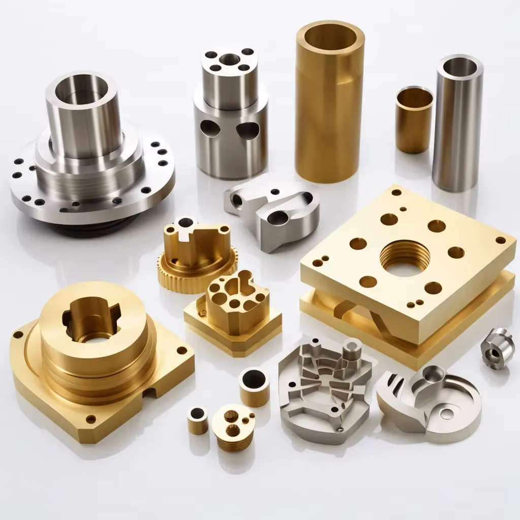
Most questions we get start with a joint that passed inspection but failed in the cell. Here is what usually happened.
Bore diameter drifts a few microns after heat and load cycles. The bearing starts to creep, the arm loses repeatability, and the cell goes down for a rework you did not schedule.
Titanium cuts hot. A tool path that leaves a sharp internal corner or a rubbing pass builds residual stress. Under reversed load the rib cracks at the fillet, not in the middle of the wall.
A joint face out of flat by 0.02 mm over 100 mm tilts the whole arm axis. The cell compensates in software, then drifts as the bolted joint settles.
Extra stock left on non-critical walls adds mass at the worst place, at the end of the arm. Motor torque and cycle time both suffer.
Three things decide whether a titanium joint survives: blank condition, thermal control during the cut, and how you measure it afterwards.
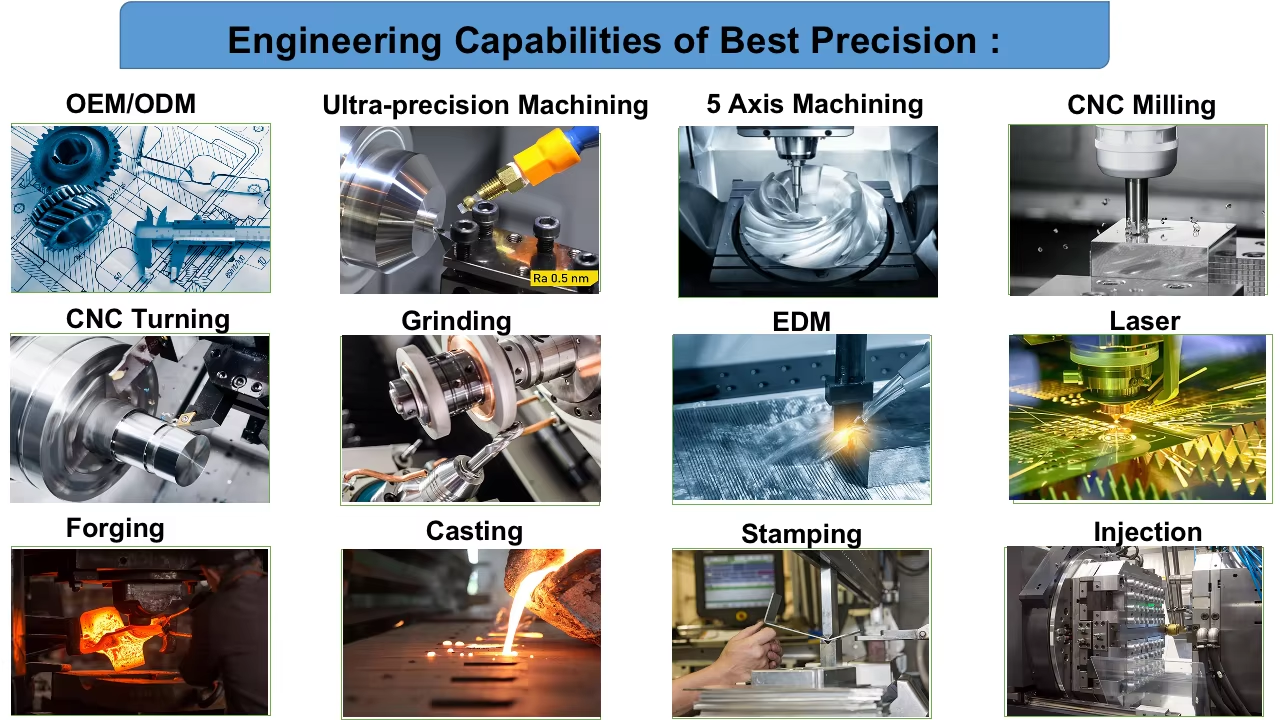
Robot arm joints are rarely a simple prism. You have a bore on one axis, a mounting flange on another, and a clevis on a third. Each re-fixture adds its own error stack. We plan the process so the critical features come off in one 5-axis setup on a Ø400 mm rotary table.
For Ti-6Al-4V (TC4) we start from forged or rolled stock with a documented mill certificate. Titanium moves when you remove material, so we leave a controlled allowance and take the finish passes after the part has cooled back to room temperature.
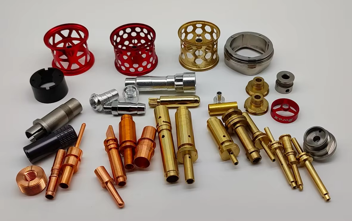
Titanium conducts heat poorly. The heat goes into the edge, not the chip, so the tool dulls fast and the part grows. We run high-pressure coolant, keep radial engagement low, and change inserts on a count rather than on a squeal.
Wall thickness under 2 mm needs a different approach again. We support the wall from both sides where the geometry allows, and we take the finishing passes in a sequence that keeps the part balanced instead of pulling it into a curve.
Pick the grade before you pick the tolerance. The two decisions are linked.
| Grade | Best for | Watch out for |
|---|---|---|
| TA1 / TA2 (commercially pure) | Cover plates, low-load brackets | Low strength; not for load-bearing pins |
| TC4 (Ti-6Al-4V) | Load-bearing joints, clevis, bearing housings | Needs rigid setups; chatter marks bores |
| Ti-6Al-4V ELI | Fatigue-critical joints, medical-adjacent cells | Higher cost; longer lead on stock |
| Inconel (alternative) | High-temperature end effectors | Much harder to cut; slower cycle |
| 6061-T6 (alternative) | Prototype joints, low payload axes | Half the strength of TC4; wears at pins |
| 7075-T6 (alternative) | Stiff lightweight links, not joints | Poor fatigue at stress risers |
Most joint projects use three or four of these, not all of them.
16 simultaneous 5-axis centers for single-setup joints, up to 4,000 mm in the long travel machines. This is the core process for clevis and housing geometry.
27 three-axis machines and 16 mill-turn centers cover pins, spacers, and turned bearing journals that pair with the machined joint body.
Check the fit and the cable routing before committing to titanium. Prototype joints can come off the same CAD in days, not weeks.
Bead blasting, tumbling, brushing and polishing. Laser marking for part IDs at a minimum character height of 1.5 mm.
12 four-axis mills handle joints with a dominant rotation axis where full 5-axis motion would not add value.
Covers, guards and cable trays that mount to the joint, so you are not sourcing brackets from a second supplier.
| Item | Capability | Note |
|---|---|---|
| Achievable tolerance | ±0.005 mm (±0.0002 in) | On critical bores and faces |
| Surface finish | Ra 0.2–0.8 μm fine; Ra 0.8–1.6 μm standard | Bearing bores usually need the fine band |
| Maximum part size | 4,000 mm | On the large-travel machines |
| Typical travel envelope | 750 × 1,150 × 550 mm | Covers most arm joint housings |
| Minimum wall | Below 2 mm with a supported setup | Below 1 mm is a design conversation |
| Order quantity | One prototype to 10,000+ parts | No minimum order quantity |
| Inspection | 100% before shipment | Reports on request |
| Lead time | Parts ship in 3–5 days | After drawing release and stock |
We have been machining in Dongguan since 2011, with a second plant in Singapore. Here is what that looks like in practice.
Three wholly-owned plants across 7,600 m², with 150 technicians on the floor. Titanium work sits inside the same quality system as our aluminum and stainless programs.
16 simultaneous 5-axis, 12 four-axis, 27 three-axis and 16 mill-turn centers. We match the machine to the joint geometry instead of forcing one platform.
Held on critical bores and mounting faces. In imperial terms that is ±0.0002 in, which is what a press-fit bearing seat actually needs.
The 16949 and 13485 scopes matter when a joint program crosses into automotive or medical-adjacent automation.
You get a quotation plus a manufacturability read within 12 hours. Production can start within 24 hours of release.
Raw material check, in-process monitoring, and final inspection on every order. Historical late-delivery probability sits below 2%.
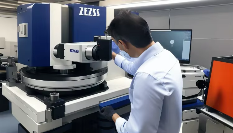
High cycle counts on the same joint, so bore wear and repeatability set the maintenance interval.
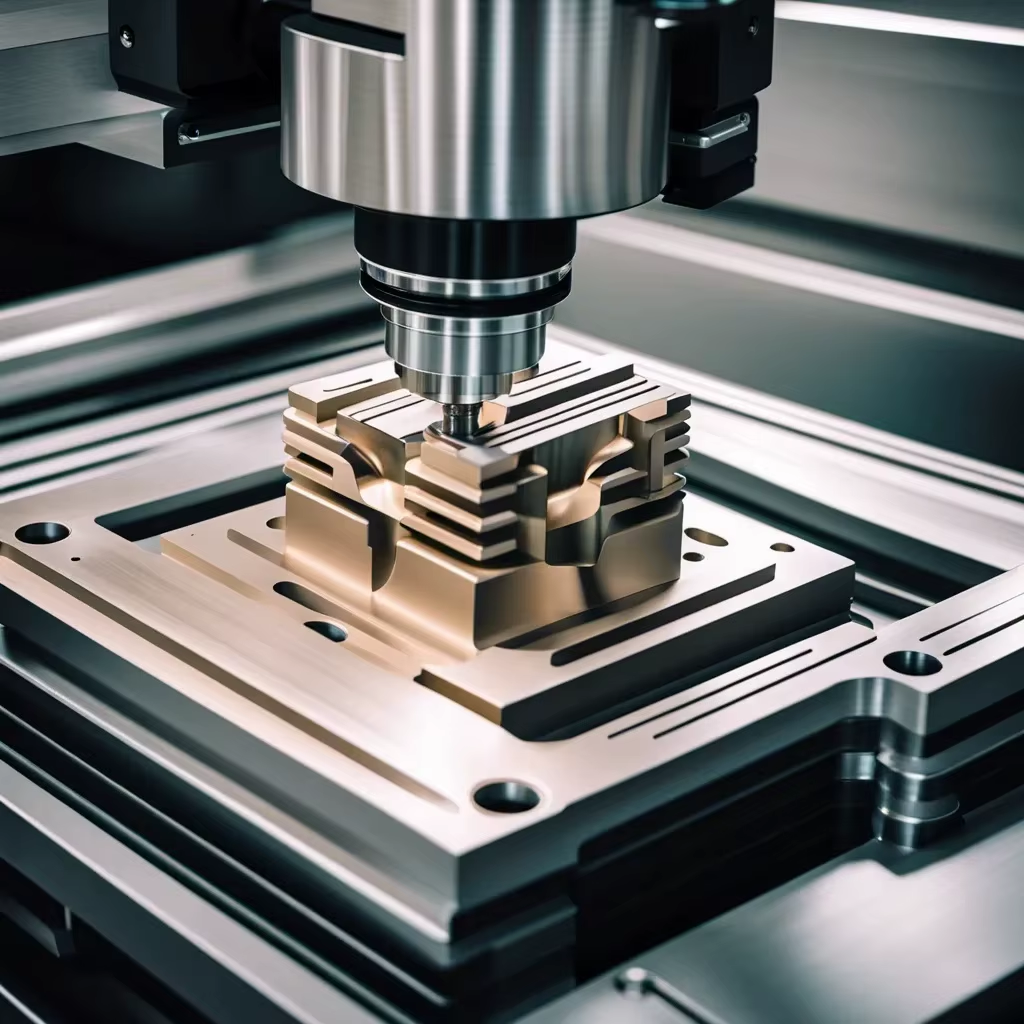
Traceable material and documented inspection matter as much as the cut itself.
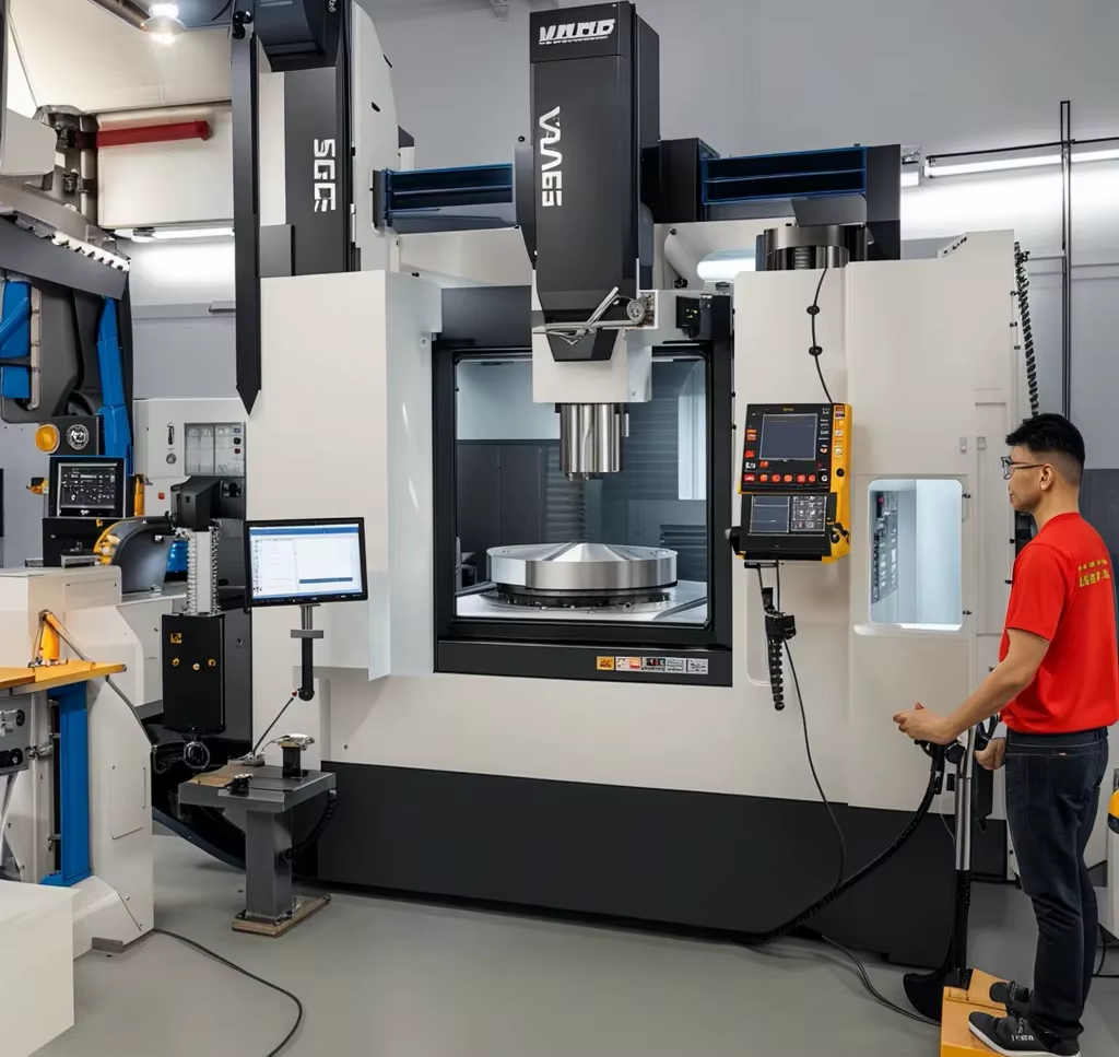
Small joints at the end of a fast arm. Mass budget and stiffness trade against each other every time.
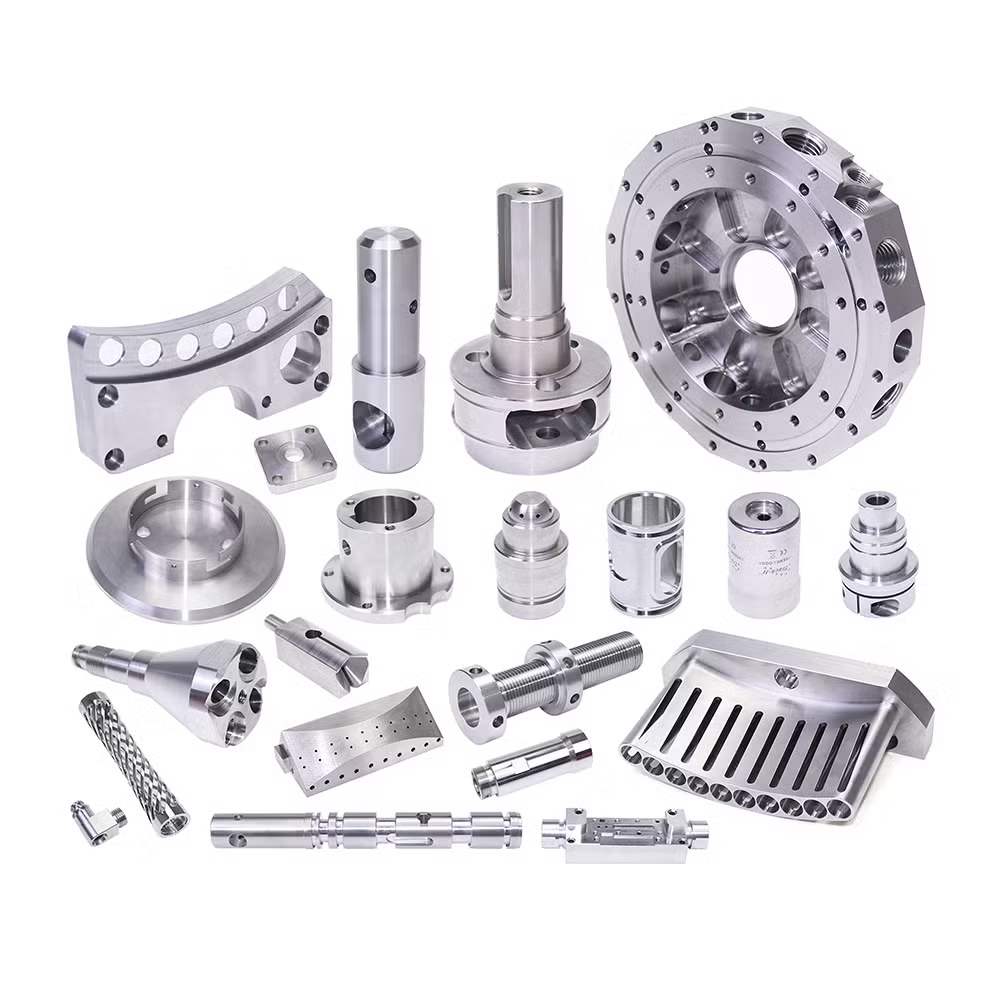
Large envelopes. The 4,000 mm travel machines take the housings that will not fit a compact center.
Use titanium when the joint carries load at a pin or bearing and you need the stiffness-to-weight ratio at the end of the arm. TC4 (Ti-6Al-4V) is the usual grade for that.
Use 6061 or 7075 when the joint is a prototype, the payload is low, or the wear surface is a separate hardened insert. Aluminum cuts faster and costs less, and for a low-load axis it is often the better call.
±0.005 mm on critical bores and faces, which is ±0.0002 in. That is achievable, not automatic. It depends on the bore depth, the wall around it, and whether the feature comes off in the same setup as its datum.
If a drawing asks for a tolerance that the geometry cannot hold, we say so in the DFM review rather than making the part twice.
Three things. Support the wall from both sides where the geometry allows, remove material symmetrically so the part stays balanced, and take finishing passes light after the part has cooled.
Below about 1 mm the conversation changes. At that point the wall is a design decision as much as a machining one, and we will flag it before quoting.
Yes. We run 16 mill-turn centers alongside the 5-axis mills, so a joint body and its matching pin or spacer can come from one supplier with one inspection record.
That matters for press fits. When two features are made to the same datum and measured together, you spend less time chasing fit at assembly.
For a press-fit bearing seat, aim for Ra 0.2–0.8 μm. A rougher bore has peaks that shear off during installation and change the interference you designed for.
For non-critical outer faces, Ra 0.8–1.6 μm is usually enough. We do not polish surfaces that carry no function unless you ask.
A 3D model or 2D drawing with tolerances, the grade, the quantity, and any finish or marking requirement. If a critical bore has a mating part, send that too.
You get a quotation and a DFM analysis within 12 hours. Uploads stay confidential, and we sign an NDA on request.
Machining runs in Dongguan, China, with a second plant at No.3 Joo Koon Circle, Singapore 629032. Parts ship in 3–5 days after drawing release and stock arrival.
The historical late-delivery probability is below 2%. We would rather quote a realistic date than a fast one we cannot hold.
Upload your CAD and specs. You get a quotation and a DFM analysis within 12 hours, with no minimum order quantity and an NDA if you need one.
12-hour quote100% inspectionNo minimum orderNDA on request
Trusted by engineers and manufacturers worldwide










Upload your 3D model or 2D drawing and get a quotation with a free DFM analysis. Maximum processing size 4,000 mm.
CNC Metals 13 grades
CNC Plastics 10 grades
Machines & processes 12 options
Surface & post-processing 10 options
Material: not selected Machine: not selected Post-process: not selected