
01
Bore and face come out out of square
A bearing bore that drifts 0.03 mm off-axis after a second setup makes the arm oscillate at every repeat point. Repositioning the part means re-zeroing, and the stack-up shows up as backlash in the field.
We machine joint housings, bearing bores and couplings for high quality robotic arm builds. One setup, one datum, tight bore-to-face geometry. First-article and final inspection reports ship with the parts.
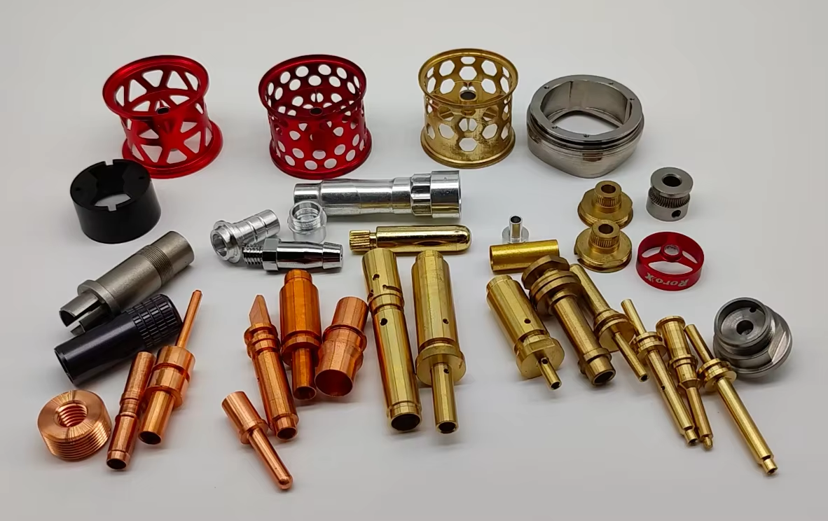
A bearing bore that drifts 0.03 mm off-axis after a second setup makes the arm oscillate at every repeat point. Repositioning the part means re-zeroing, and the stack-up shows up as backlash in the field.
Thin walls deflect under clamp pressure. If the housing is machined in three ops, the wall on one side scallops. The joint still fits, but stiffness drops and the arm loses repeatability under load.
Bore, face, bolt pattern and dowel holes all carry their own tolerance. Machine them in separate setups and the errors add up. The arm passes bench test, then fails cycle testing after a few thousand moves.
A bore left at Ra 3.2 μm wears the seal lip faster than one at Ra 0.8 μm. The leak shows up months later, and by then the whole joint has to come off the arm.
The bore, the face and the bolt pattern come off the same setup so the stack-up stays inside ±0.005 mm.
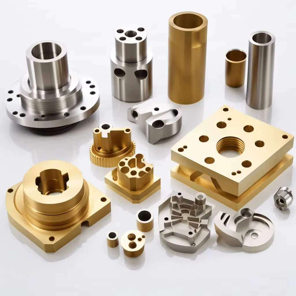
A robotic arm joint is a stack of features that only work together: bearing bore, mounting face, bolt circle, dowel holes, seal groove. Cut them in three operations and each re-clamp adds error. On our 16 simultaneous 5-axis machining centers, the part stays on one fixture from roughing to finishing. The rotary table indexes to the next face instead of the operator moving the part.
That matters most on parts with an angled axis. A joint housing at 45° to the mounting face is awkward on a 3-axis mill and needs a custom angle plate. On a 5-axis center the table tilts to the feature and the tool reaches it in one pass. We hold ±0.005 mm on bore position and perpendicularity across the joint body.
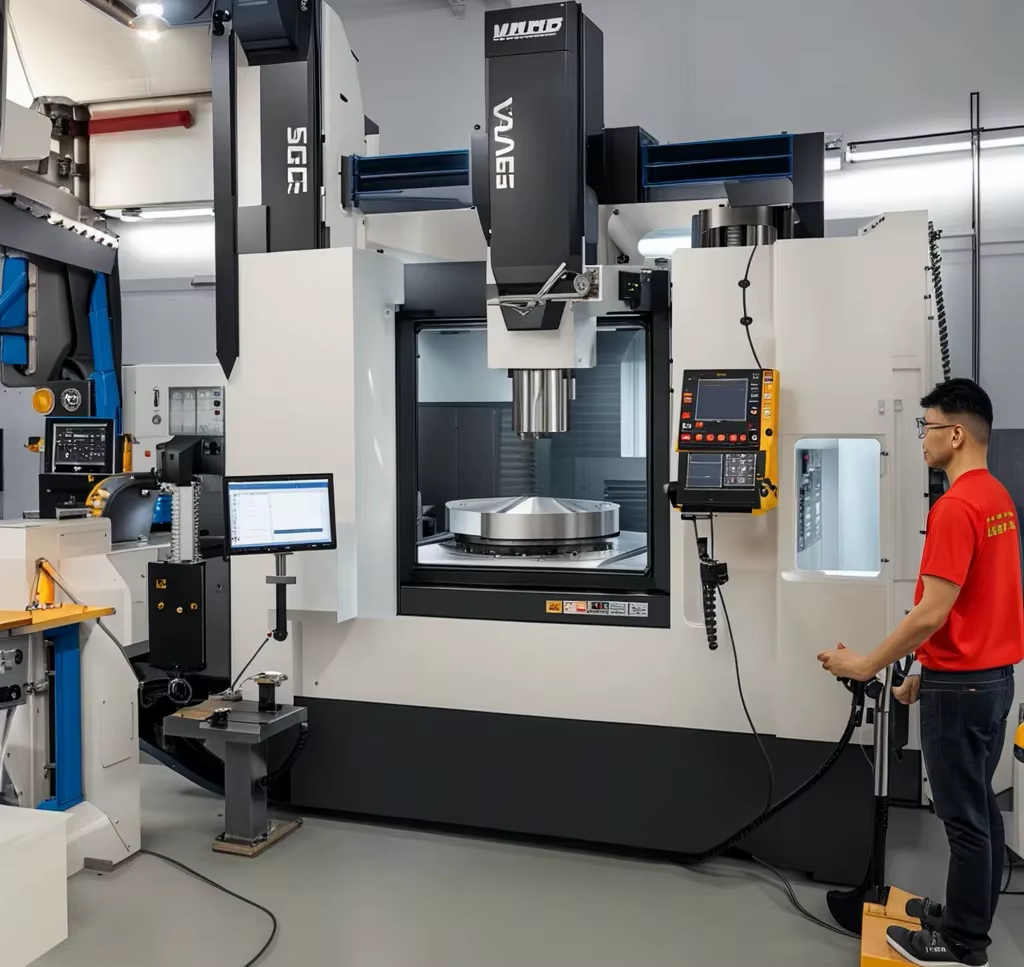
Joint housings are usually thin-walled aluminum or titanium. Clamp too hard and the wall springs back after unclamping, so the bore measures round on the CMM and out-of-round once it is free. We rough with light radial engagement, leave 0.3 mm for finishing, and let the part cool before the final pass.
Bore finishing is a separate step with its own parameters. A reamer or a boring head with a fine feed, depending on the diameter and the surface finish called out on the drawing. Standard output is Ra 0.8–1.6 μm; where a seal runs, we finish to Ra 0.2–0.8 μm.
Pick by feature count, wall thickness and bore tolerance.
| Joint type | Best route | Why |
|---|---|---|
| Compact wrist joint, Ø80–150 mm | 5-axis, one setup | Bore and angled face in one datum |
| Thin-wall aluminum housing | 5-axis + stress-relief | Keeps wall round after unclamping |
| Bearing bore under Ø50 mm | Mill-turn + fine boring | Roundness held to half the tolerance |
| Large base joint, over 1,000 mm | 5-axis on 4,000 mm travel | One part, no splice or weld |
| Prototype bracket, 1–20 pcs | 3-axis + 5-axis finish | Lower setup cost at low volume |
| Titanium joint, high load | 5-axis, slow speeds | Heat kept out of the thin sections |
Bearing bores, mounting faces and bolt circles cut in one setup on 5-axis centers.
Spline and keyway fits, pilot diameters, dowel holes held to drawing.
Bore roundness and perpendicularity to the mounting face.
Pocketed bodies with thin walls, finished without distortion.
Low-volume runs from one prototype upward, no tooling charge.
Machined prototypes in 3–5 days to check fit before tooling.
| Item | Range | Notes |
|---|---|---|
| 5-axis centers | 16 simultaneous | Ø400 mm rotary table |
| Maximum part size | 4,000 mm | 4,000 × 400 × 150 mm travel |
| Tolerance | ±0.005 mm | ±0.0002 in |
| Surface finish | Ra 0.2–3.2 μm | Ra 0.8–1.6 μm as standard |
| Aluminum | 6061, 7075, 2024, 6082 | Anodizing available |
| Stainless | 303, 304, 316L, 17-4PH | Passivation on request |
| Titanium | TA2, TC4 (Ti-6Al-4V) | Slow speeds, controlled heat |
| Order quantity | 1 to 10,000+ | No minimum order quantity |
Bore position and perpendicularity checked against the drawing, not against a sample.
Raw material check, in-process monitoring and final inspection on every batch.
We return a quotation and a free DFM analysis within 12 hours of receiving files.
Once the drawing is signed off, machining can start within 24 hours.
Standard parts ship in 3–5 days after production start.
ISO 9001:2015, IATF 16949:2016, ISO 13485:2016, ISO 27001:2022.
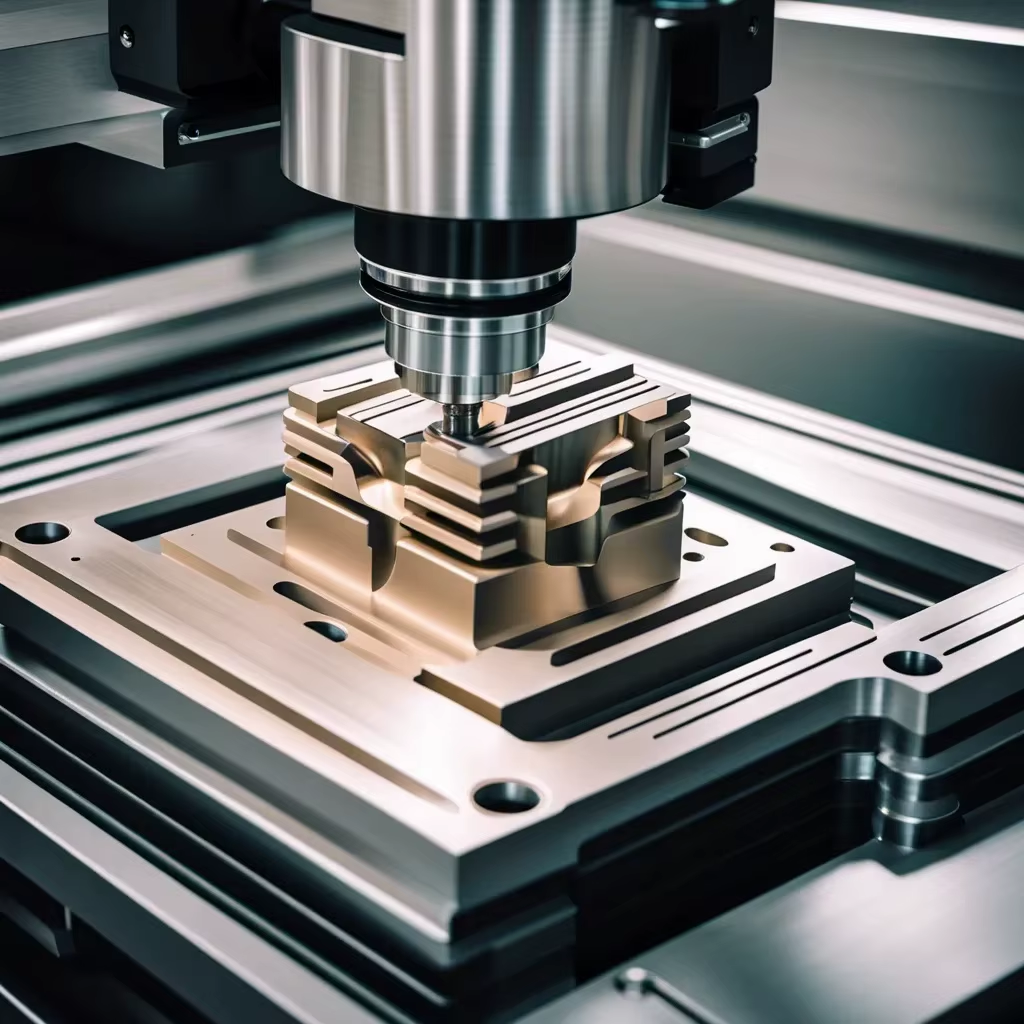
Joint housings and couplings for arms with repeatability requirements in the tens of microns.
Actuator bodies and brackets where traceability and material certificates are part of the order.

Heavy base joints up to 4,000 mm machined in one piece, no splice or weld.
Count the faces the part has to be clamped on. If the bearing bore, the mounting face and the bolt pattern sit on three different planes, a 3-axis mill needs three setups and each re-clamp adds error.
If the joint has an angled axis or a compound angle, 5-axis is usually cheaper than building a custom fixture, even at low volume.
±0.005 mm is our standard capability, and we hold it on bore position and perpendicularity. On a thin-wall part, the limiting factor is often the wall itself, not the machine.
When the wall is under 3 mm, we rough, let the part cool, then finish with light cuts. If the drawing tolerance is tighter than the wall can hold, we tell you before machining rather than after.
6061-T6 and 7075 cover most aluminum joint housings. 7075 gives higher strength where the wall is thin. 6082 is common in Europe and machines well.
For higher load or corrosion resistance, 17-4PH stainless and TC4 titanium are both in stock. Titanium needs slower speeds and more attention to heat in thin sections.
Yes, up to 4,000 mm. The large 5-axis centers have 4,000 × 400 × 150 mm travel, so a base joint that would otherwise be welded can be cut from solid.
One piece removes the weld inspection step and the distortion that comes with it. It also means the bore and the mounting face share a datum.
A 3D model and a 2D drawing with tolerances, material and finish. If the drawing is not finished, send the model and tell us the function of each critical feature.
We return a quotation and free DFM analysis within 12 hours.
Standard output is Ra 0.8–1.6 μm. Where a seal or O-ring runs, we finish to Ra 0.2–0.8 μm and check the bore with a profilometer.
If the drawing does not specify finish, tell us where the seal sits and we will set the parameter accordingly.
Uploads are secure and confidential. An NDA is available on request before you send files.
We are certified to ISO 27001:2022 for information security management.
No minimum order quantity. We run from one prototype to 10,000+ part runs on the same process.
Prototypes ship in 3–5 days so you can check fit before committing to a production run.
We return a quotation and free DFM analysis within 12 hours, inspect every part before shipment, and run from one piece upward.
12-hour quote100% inspectionNo minimum order quantityNDA on request
Trusted by engineers and manufacturers worldwide










Upload your 3D model or 2D drawing and get a quotation with a free DFM analysis. Maximum processing size 4,000 mm.
CNC Metals 13 grades
CNC Plastics 10 grades
Machines & processes 12 options
Surface & post-processing 10 options
Material: not selected Machine: not selected Post-process: not selected