Recreating a part or product without schematics or digital design files used to be a daunting task. existBefore 3D scanning technology was widely available, reverse engineering involved manually taking precise measurements of objects to create designs.
Now everything has changed, with affordable prices3D scanning technology, easier-to-use software, and 3D printers can quickly produce models, prototypes, and in many cases, final parts.

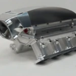
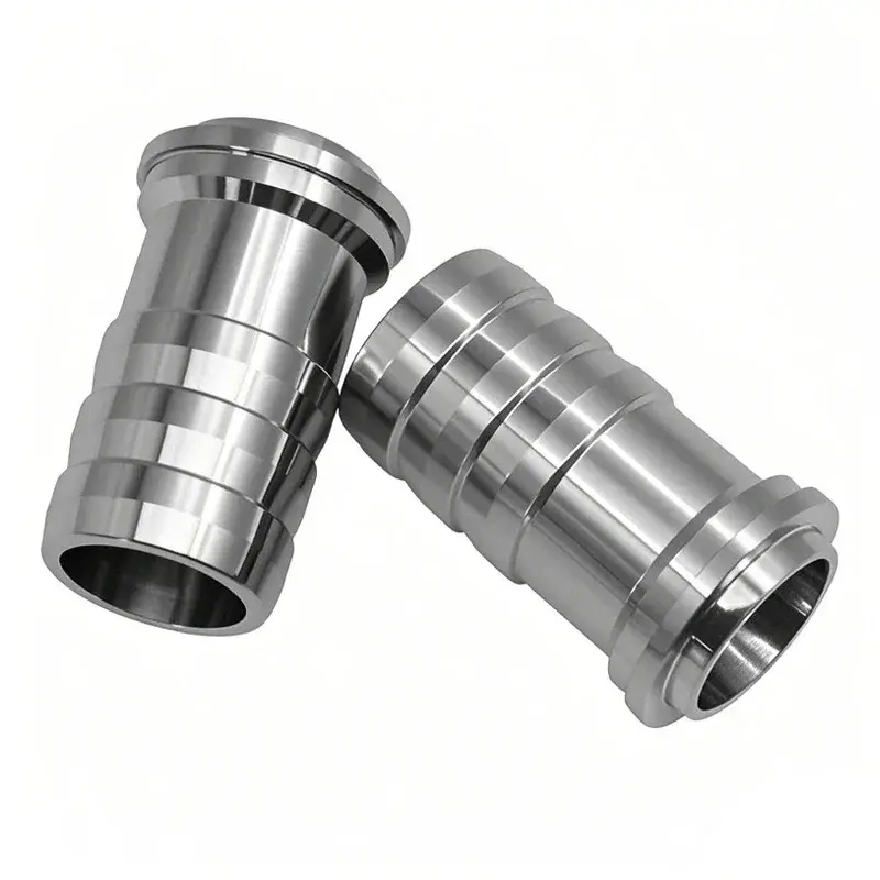
to useReverse engineering of parts using 3D scans is common among global engineering companies such as Sulzer (left) and specialist reverse engineering companies such as Aeroscan (right).
What is reverse engineering?
Generally speaking, reverse engineering involves taking an object apart to understand how it works. Concretely, reverse engineering consists of measuring physical objects and then reconstructing them digitally.The 3D model can then be 3D printed or manufactured in another way.
In this article, we’ll walk you through the process from physical part to final digital model, demonstrating key steps and key tooling options along the way.
But first, let’s look at what reverse engineering is used for today.
Applications of Reverse Engineering

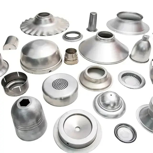
In a sort of reverse engineering process, use3D scanner captures 3D measurement data across the entire surface to facilitate mold manufacturing in foundries (Source: Capture3D)
Remaking spare parts and tools that are no longer in production is an obvious use of reverse engineering, but it can be used for much more than that.
Improve old parts and products
Today, many companies still use molds from decades ago to make parts, while the original designs and design decisions have been lost to time. With digital models, you can improve old parts to make them stronger or lighter. Perhaps the original design was developed before the advent of today’s sophisticated simulation and generative engineering software capable of virtually testing the stress response and its use.AI brings improvements.
After-sales customization
In the automotive industry in particular, providing products and accessories that are perfectly matched to your new car is an important business. To do this, manufacturers need precise measurements, and3D scanning is the fastest method. You may not always make these models, but it is common to 3D print prototypes for test fit and assembly.
Digitize handmade prototypes
Artists, designers and automakers are still shaping their concepts with clay, but once styles are approved, it’s time to move those products into production, starting with digital mockups. Once scanned and digitized, these models can still be modified and pressure simulations performed.

3D scanning can be used to create sculpture molds to reproduce artwork (Source: Shining 3D)
Protect monuments
3D scanners have become standard equipment in the world’s largest museums for the protection of cultural heritage. The extensive digital library houses masterpieces of art and antiques, some of which are presented virtually online to a wide audience, while others are carefully reproduced for display, allowing the originals to be preserved in completely safe.
Jewelry and Art Reproductions
Nowadays, reproducing antique jewelry or memorabilia is easier than ever. Scan originals and scale them to the desired size, or scan to archive them in case of fire or loss.
product inquiry
Companies often reverse engineer their competitors’ products to understand their manufacturing processes, discover their strengths and weaknesses, and learn from their innovations. Of course, remanufacturing of products is subject to copyright, trademark and intellectual property restrictions. Reverse engineering is also used to study how an event, such as a car accident, occurred by performing3D scan and compare the digital model with a digital model of the new car.
reverse engineering3 main steps

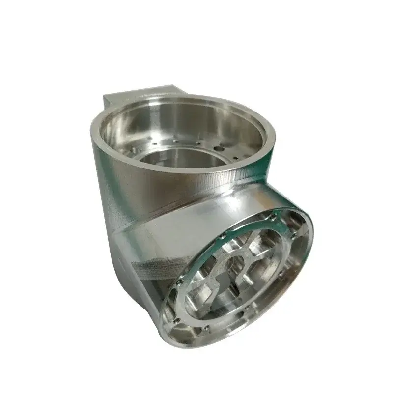
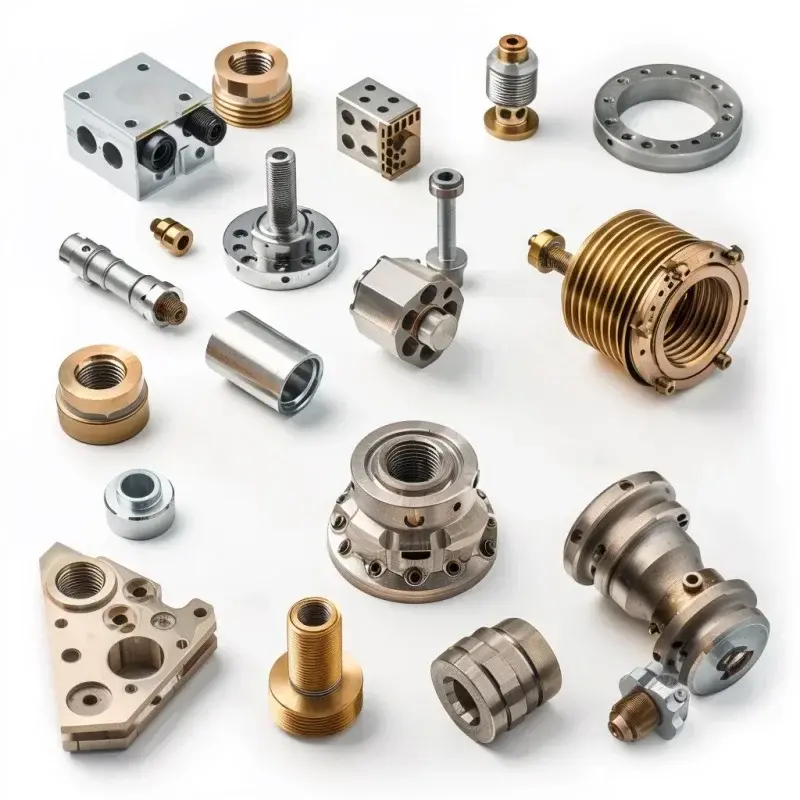
Reverse engineering of industrial parts offers the possibility of improving and modifying the part (source:Take off 3D)
The reverse engineering process follows a standard workflow, which may vary slightly depending on the specific tools used and the desired results. Generally speaking, the process is as follows:
Data collection:There are many ways to collect dimensional data. Currently, the most commonly used method is3D scanning, which we will present in detail below.
Computer science:SinceThe data obtained by the 3D scanner is transformed into a digital model. The original 3D model often requires some work to correct and refine certain areas that may not have been correctly captured during the scan.
Construction of models:The specific actions taken here depend on the expected results of the reverse engineering. If the goal is simply to copy, then the part is ready to be manufactured. If repairs and additions are necessary, the digital model is processed in computer-aided design software.
pass3D scan to obtain data

Scantech’s Simscan is a popular palm-sized handheld 3D scanner that uses lasers to measure and record surfaces (Source: Scantech)
different types3D scanning technology uses different methods to capture data. They vary greatly in size and price, from portable devices to large fixed systems. Each technique has its advantages and disadvantages and should be chosen based on the size and type of object being scanned.
Reverse engineering often uses optical methodsA 3D scan (using structured light or laser beams) is performed. These scanners use light triangulation and sensors to collect the reflection angle of laser light. Considering the distance between the scanner and the object, the scanning hardware can map the surface of the object and record points to form a 3D scan. 3D scanning can capture the precise location of millions of points on a part every second, generating enormous amounts of data.
These optics3D scanners are known for their precision, with resolutions reaching tens of microns. But on the other hand, their measurement range can be limited to a few meters.

Photogrammetry from photos3D scanning is mainly used for digital models of virtual displays, and there is often not enough data for reverse engineering (Source: 3DF Zephyr)
photogrammetryis another kind3D scanning technology stitches together photos from different angles to form a three-dimensional object. The technology relies heavily on software that processes hundreds of photos to generate 3D models. As smartphones become more powerful, photogrammetry is becoming increasingly popular because photo taking and processing can be done right in the hand.
Although this new technology is ideal for producing digital colors3D models can be viewed online, such as product images, but the data you get from a smartphone app is not of sufficient quality to perform true reverse engineering because the amount of data is too small or you need to do more work in a CAD Program.
Data processing for reverse engineering

A wire mesh of the bust of Ajax digitized by the Lincoln Preservation Group, which used3D scanning technology precisely scans the surface geometry of artifacts and architectural elements (Source: Lincoln Preservation)
Now that you’ve selected the scanner best suited to your application and budget and scanned your objects, what’s the next step?
Unfortunately,3D scanners collect data points on physical objects; they do not create digital models that can be directly manufactured. There is a common misconception that optical 3D scanners produce digital models. There is another software step between the scanned data and the model that can be manufactured.
In fact, popularCAD programs such as Autodesk’s Fusion 360 or Dassault Systèmes’ Solidworks cannot read raw data directly from a 3D scanner: it must be converted into a model that those CAD systems can recognize and process. (Solidworks of course has a feature called ScanTo3D, but it’s limited to working with low-resolution 3D scan data and is not suitable for reverse engineering.) Let’s explain.
The more points there are in the “point cloud” (raw scan data), the more accurate the model will be. (See the dental scan point cloud in the image below.) Accurate scan data can save a lot of time in the CAD stage. Low resolution data can give you a general idea to plot, but you are essentially recreating the part. On the other hand, your application may not require all of these points.

Dental scan point cloud data in Afanche3D software (Source: Afanche3D)
Equipment Sales in Portage, MI and“It is always possible to reduce the size of the point cloud by reducing the spacing between points in the scanner software,” said Mike Spray, owner of 3D scanning service provider Laser Abilities.
The software that comes with the scanner is the first place to start editing the data, he said. Once the point cloud is cut, the scanner software can convert the point cloud to a model, orA 3D mesh made up of thousands or even millions of tiny triangles or other polygons.
The software uses algorithms to“Interprets” point data, in many cases, filling in gaps when the scanner does not capture enough object data, such as when a surface is too bright and interferes with the scanner’s light. That’s why software companies tout the power of their attribute algorithms and other “smart” features designed to correct any anomalies in point cloud data. Take a look at the scanned data plot below and the “cleaned” model processed using Artec Studio software from 3D scanner manufacturer Artec 3D.

Scanning software (eg.Artic Studio) uses algorithms and artificial intelligence to clean up anomalies and generate more complete scan models (Source: Artec 3D)
A few3D scanner manufacturers, such as Artec, Evixscan, Faro and Zeiss, have developed sophisticated software to accompany their hardware. Although these software cannot completely replace CAD software, they have made great strides in converting scanned data into CAD models. Other scanner manufacturers, like Evatronix, outsource the interpretation step to third-party programs, like the popular Geomagic. We describe all of these procedures in the following sections.
Spray says: “Starting with a full or ‘watertight’ mesh, you can go in different directions. The mesh can be exported as an STL file directly to the 3D printer’s slicing software. The mesh does not have to of actual thickness but can be applied to an STL file » From there, just click print.
This slice mesh process is used to create an exact physical copy of an object. For example, you can use this method to print a product used as a prototype to test its fit with another component.
However, with most reverse engineering, there are more steps because the scanned product may need to be repaired or modified before it can be manufactured. Depending on the quality of the data collection or the accuracy of the scanner, the model may require correction, cleaning, refinement, or even some minor surface adjustments.
For example, to make a tool, modifications are necessary depending on the manufacturing method.“If you’re doing molding or injection molding, you need to increase the draft so the part can come out of the mold,” says Spray. “You may want to add three or five degrees of draft to the part. This will not be included in your scan data.” Likewise, some metal 3D printing methods require you to account for shrinkage during the manufacturing process.
Matching reverse engineering goals to software is not always easy. in general,The software that comes with the 3D scanner will do the trick. Sometimes a lot of CAD program time can be saved between the scanner and the CAD program by using a specially created program to edit the scanned data.
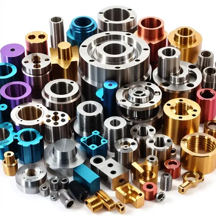
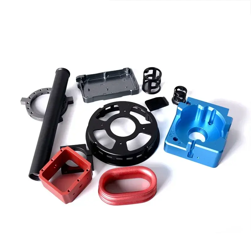
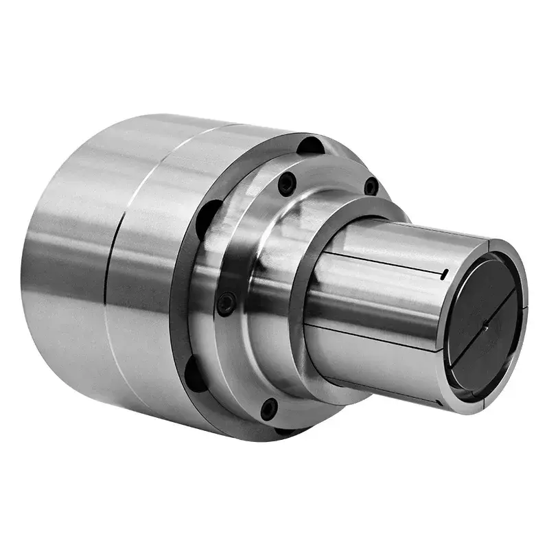
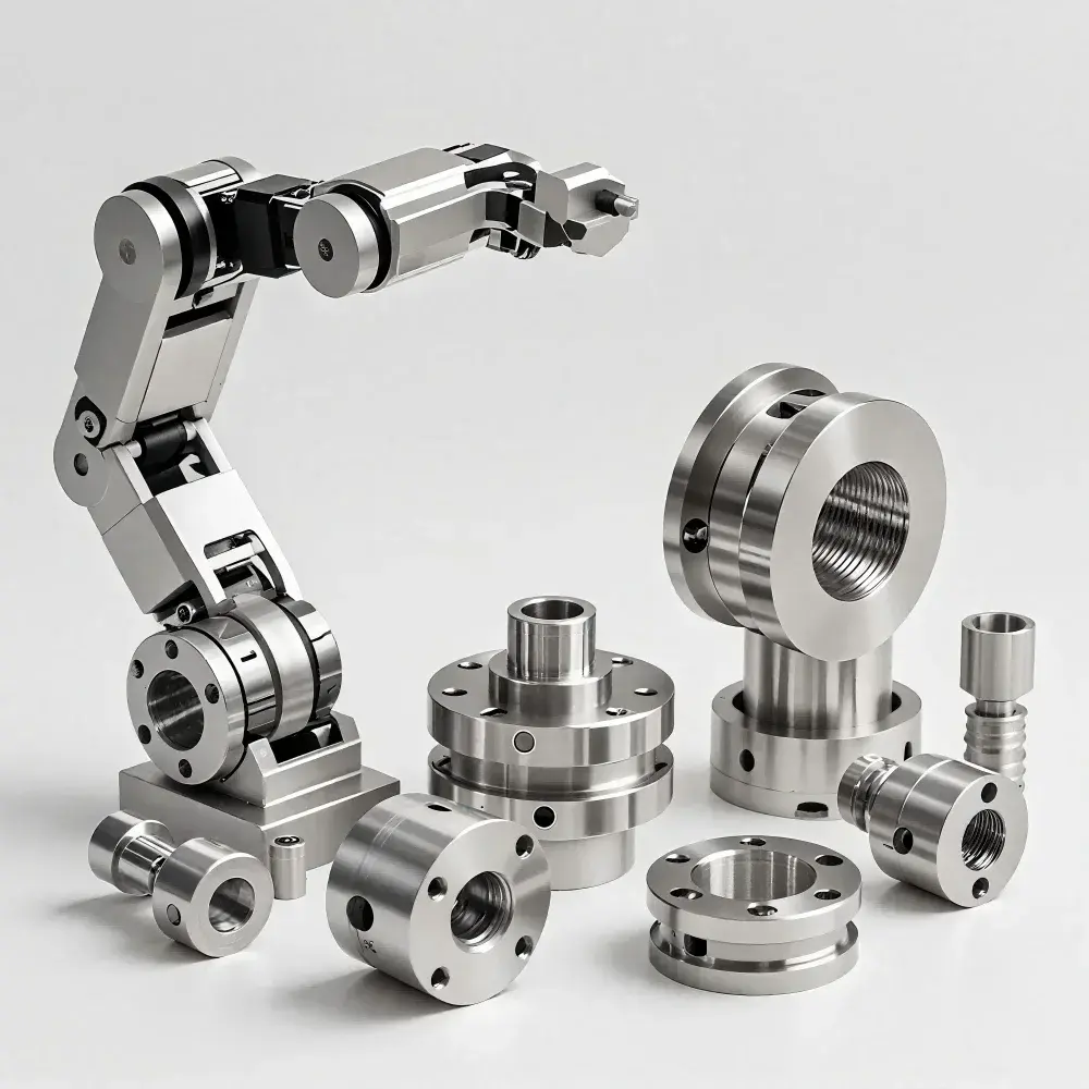
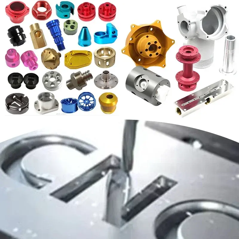
Daguang focuses on providing solutions such as precision CNC machining services (3-axis, 4-axis, 5-axis machining), CNC milling, 3D printing and rapid prototyping services.