Freeing Fast Electronic Prototyping: Your Final CNC PCB Milling Guide
In the fast-paced electronic design world, rapid prototyping is not only convenient, but essential. Traditional PCB manufacturing often involves lengthy waits and minimum order quantity and kills innovation. Input CNC PCB Milling: Desktop Manufacturing Revolution that allows you to convert digital designs into functional circuit boards Hournot a few weeks. This guide uncovers the mystery of the DIY process while highlighting when to use professional CNC machining services such as Greatlime to deliver more demanding projects.
Why CNC milling beats traditional PCB Fab for prototyping
- speed: From CAD files to transfer from CAD files to completed board within one hour – Perfect for same-day debugging.
- Cost-effective: Eliminate the establishment fees and transportation costs of the board of directors of 1-10.
- Instant iteration: Test design flaws? Modify the file and grind a revision immediately.
- Material flexibility: No supplier delays for mill-specific substrates (FR-4, RF materials, or even aluminum materials).
- Complete control: Completely internally handled sensitive or proprietary design.
DIY CNC PCB Milling Workflow: Step by Step
1. Design and Document Preparation (CAD):
- Use industry standard software (Kicad, Eagle, Altium) to design your schematic and PCB layout.
- Key steps: Export Gerber files (RS-274X) and Excellon Drill Files. Double check layer alignment!
2. Cam handling and tool routes:
- Import Gerber/Excellon files into CAM software (FlatCam, BCNC, commercial options).
- Define processing parameters:
- Bit selection: Traces are engraved with special V-shaped PCBs (including angles of 10°-60°). Carbide end mill for drilling/cutting (0.8mm-2mm).
- depth: Set the exact engraving depth to copper (usually 0.05mm-0.1mm) and cut depth (full plate thickness).
- Feed and speed: Optimize RPM (usually 24,000-60,000 rpm) and feed rate (400-800 mm/min) according to bit/material. hint: Too slow = burning substrate; too fast = broken tool.
3. Machine and material settings:
- Fixed blank: Use strong double-sided tape or vacuum meter to adhere to FR-4 (or other substrate) on the machine.
- upgrade: Perform meticulous bed-level routines. Surface inequality is the main reason for debris breakage and poor definition of traces.
- Tool Zero: Use the sensor accurately or manually to set the Z-axis zero point on the copper surface.
4. Milling execution:
- Run the tool path in this order:
- drilling: VIA/Component Hole.
- Engraving/isolation: Cut marks and isolate copper areas.
- Cut out: Analyze the board outline.
- Monitor: Watch the initial pass closely. Use dust collection/shutter for security and chip management.
5. Post-processing:
- Deburring: Use a beautiful sandpaper or fiberglass pen to gently remove rough edges around the marks.
- clean: Remove copper dust with isopropyl alcohol and compressed air.
- Surface preparation (optional): If necessary, apply a solder mask (resistant to UV) or a wire mesh screen.
Overcome the ordinary DIY CNC milling challenge
- Broken bits: Caused by wrong Z height, dull tools, excessive feed or debris. Solution: Detailed setup, sharp position optimized for PCB, conservative initial feed, air explosion.
- Incomplete trace isolation: The bed or material is warped unevenly. Solution: High quality substrate, perfectly flat, considering a depth edge Deeper, check the cam isolation width.
- Rough edges/burrs: blunt tool or incorrect rpm/feed ratio. Solution: Always use sharp PCB specific bits for optimizing speed and feeding.
- Copper lift: Too much heat or depth. Solution: Ensure cooling (air assist!), check feed rate, and use high-quality enclosure plates.
When your DIY project requires Pro-grade CNC Power
Although desktop mills work brilliantly with rapid prototypes and simple double-layer boards, complex designs require industrial capabilities:
- Multi-layer board (4 layers): Accurate layer alignment (register) and plating through plating – Beiyuan DIY range.
- High-density interconnect (HDI): Microvaccine and ultrafine tracks (<0.1mm) require submicron accuracy and advanced examination.
- Harsh materials: Aluminum substrates (IMS), exotic RF laminates (Rogers) or thick metal backing require rigid machines and specialized tools.
- Quantity production: How many boards surpass? Professional CNCs are faster and more cost-effective.
- Extreme tolerance requirements: Five-axis accuracy is required for aerospace, medical or high-frequency applications.
Why Greatlight enhances your premium PCB manufacturing
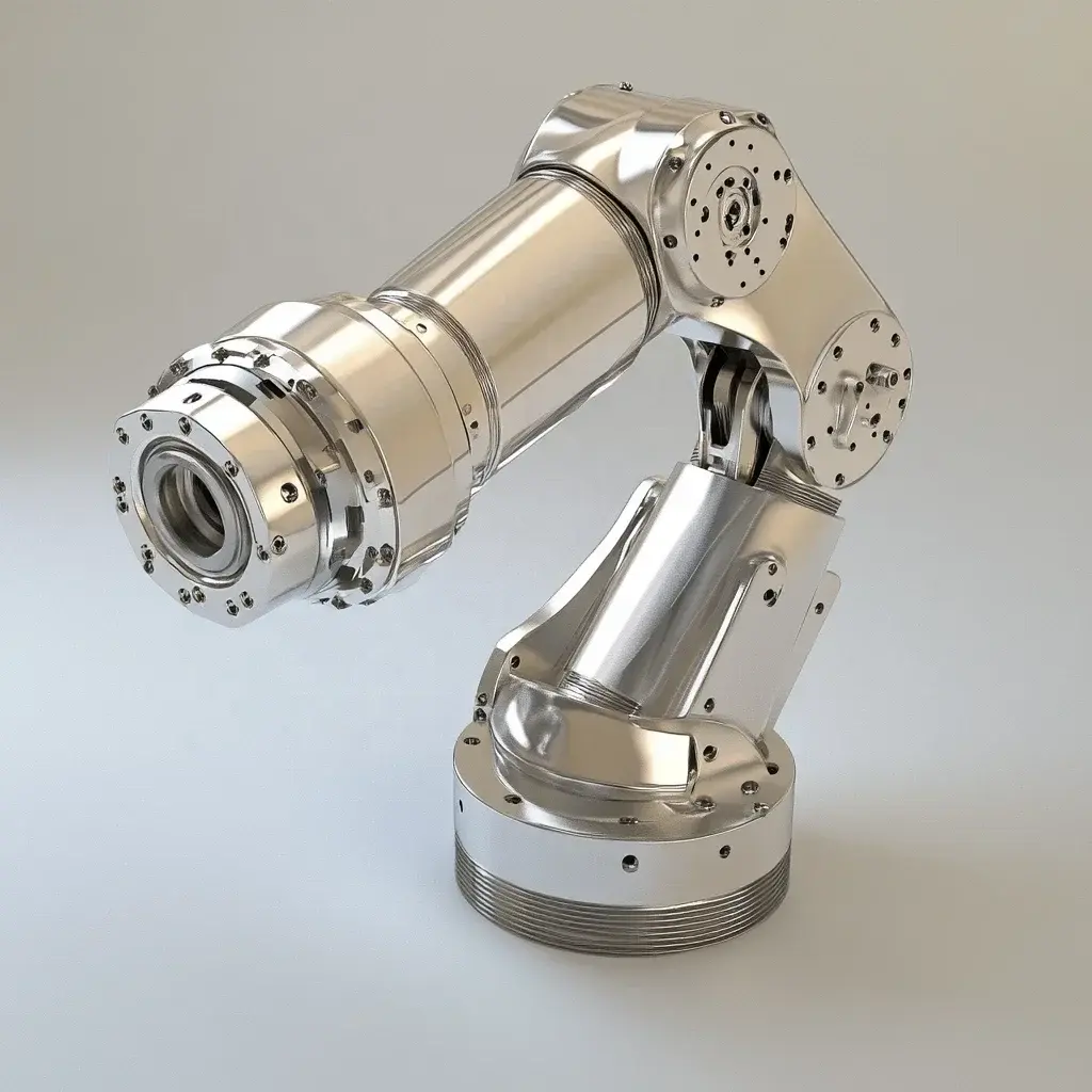
At Greatlight, we bridge the gap between prototype innovation and production reality. As a leader Five-axis CNC machiningWe solve complex manufacturing challenges outside the scope of desktop mills:
- Unparalleled precision: Five-axis dynamics enable complex contours, deep pockets and drilling at composite angles and drilling on standard 3-axis mills. Ideal for advanced RF housings, radiator integration or intricate fixtures/fixes.
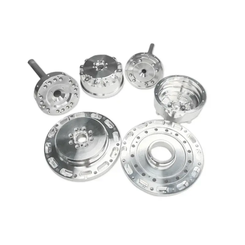
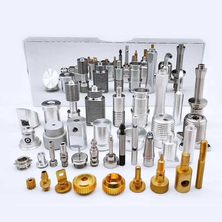
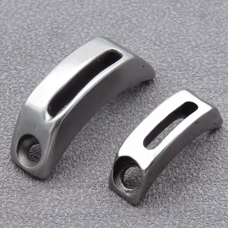
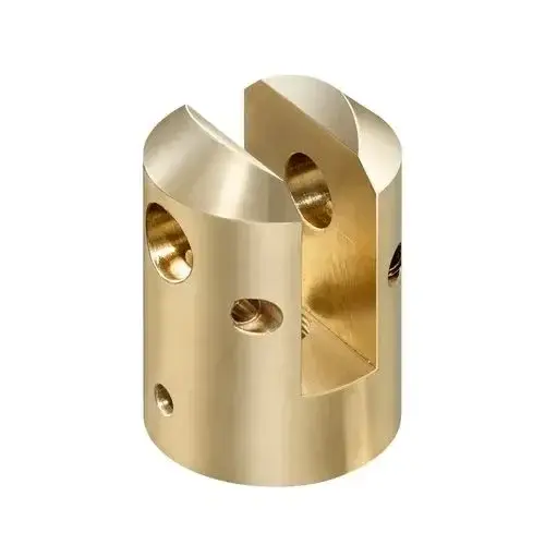
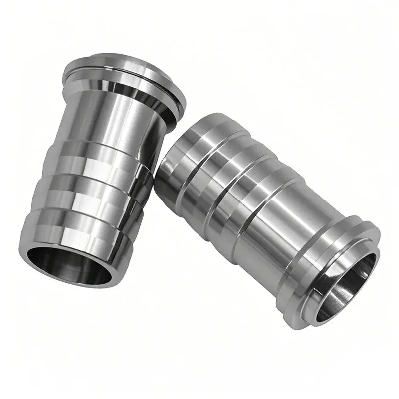
- Material Master: We skillfully machine a wide range of metals (aluminum, copper alloy, stainless steel, titanium) and rigid plastics, which are essential for durable housings, differs and RF shields integrated with PCBs.
- A true one-stop service: In addition to milling the original PCB:
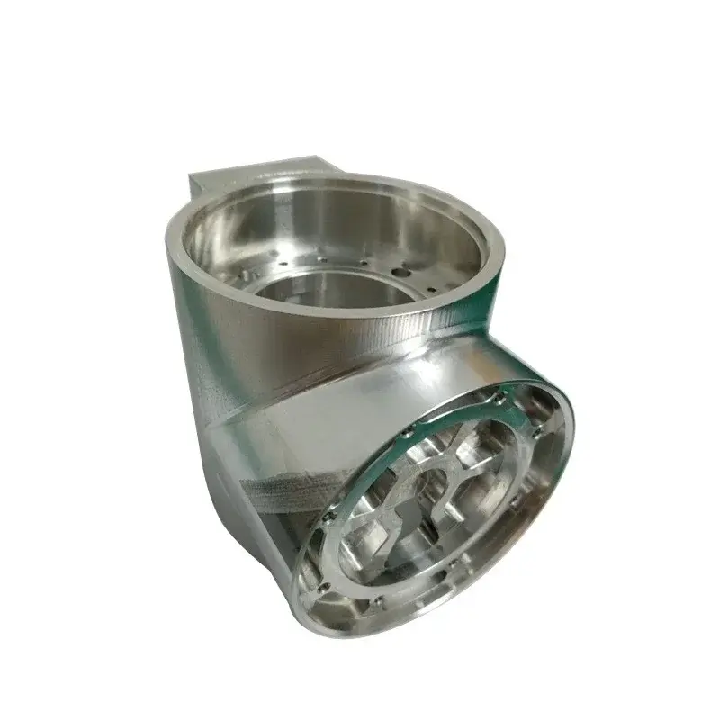
- Complex metal shell: Complete shielding solution is processed to tolerances within ±0.01mm.
- Thermal management: Custom radiator made from solid copper or aluminum and has an optimized fin structure.
- Integrated components: Accurate mounting plates, connectors and mechanical components.
- Complete post-processing: Anodizing, electroplating, laser marking, powder coating.
- Speed and reliability: Leverage our advanced equipment and process expertise to turn around quickly to ensure tight deadlines are completed on time.
- Scalability: Seamless transition design from prototype to mass run without the hassle.
Give you the ability to build:
Don’t let manufacturing constraints limit your vision. Contact Greatlight to get a quote and experience our Five-axis CNC machining expertise Provide precision metal parts, components and integrated solutions by time and budget. Get your custom precision parts now!
Conclusion: Bridging the prototype production gap
CNC PCB milling is a transformative tool for modern electronics manufacturers, hackers and engineers to achieve unprecedented speeds in the prototype cycle. Mastering the DIY process will unlock fast design verification and small batch production. However, recognizing its limitations is key. Working with a professional five-axis CNC machining provider such as Greatlight ensures manufacturing, reliability and performance when projects require multiple layers of complexity, extreme accuracy, professional materials or scalability. By combining DIY agility with professionally manufactured muscles, innovators can conquer any electronic design challenge at any scale.
CNC PCB Milling and Machining: Answer your questions (FAQs)
Q1: What is the minimum trace width/pad that I can reliably achieve with DIY CNC PCB milling?
one: With careful adjustments (using sharp 30°-20°V bits, perfect upgrade, rigid machine), you can reach 0.2mm (8MIL) of trace/space. Consistently hitting 0.15mm (6 million) or below requires excellent conditions and is prone to problems. For intensive designs, consider using DIY milling, but outsourcing the final production.
Q2: Can I mill a double-sided PCB on a DIY CNC?
one: Yes, but aligned (Register) is crucial and challenging. For DIY, 4 layers are not practical. Professional services are better for complex multi-layer boards that require plated and precise alignment.
Q3: My milling marks look rough or uneven. What causes it?
one: Common culprits: dark cutters (replace!), incorrect spindle speed (optimized RPM), too high feed rate (slow!), vibration in the machine frame (ensure stiffness), unstable material fixation, uneven bed or insufficient dust extraction, resulting in debris recovery.
Q4: Why choose FR-4 instead of other materials for milling PCBs?
one: The FR-4 is standard: affordable, ready to use, good electrical performance, and relatively easy to clean. Alternatives such as FR-2 (phenols) are cheaper, but are more prone to tearing. Flex polyimide or RF laminates (Rogers) are critical for a specific application, but are expensive and challenging for consistent milling.
Question 5: When is it absolutely necessary to use professional 5-axis CNC services, such as Greatlight for PCB-related parts?
one: Consider professional 5-axis CNC when needed:
- Complex 3D geometry (non-slab surface, complex shell).
- Close tolerance (<±0.05mm) on metal parts (shielding, radiator, connector).
- High volume production operation.
- Multi-layer (> 2-layer) PCB manufacturing, including electroplating.
- Harsh processing of materials (metal composites, thick copper cladding, ALSIC for thermal management).
- Integrate PCB installation and mechanical functions into a single precision component.