Unlock Quick Prototyping: Your Comprehensive DIY Guide for CNC PCB Milling
The journey from circuit design to functional printed circuit boards (PCBs) is often like a bottleneck for hardware developers and electronics enthusiasts. While using design for manufacturing is conventional, turnaround time can kill iteration and rapid prototypes. This is where the DIY CNC PCB milling steps are located – a powerful technology that allows you to convert digital designs into physical boards on a workbench. This guide takes a deep dive into the world of CNC PCB milling to enable you to master this skill.
Beyond Etching: Why Choose CNC Milling for PCBs?
Traditional chemical etching has its place, but CNC milling provides obvious advantages for prototyping and low-capacity production:
- Speed to prototype: From the finished design on a computer to the physical board that prepares components in hours rather than days or weeks.
- Design iteration freedom: Test the design immediately without waiting for an external factory building. Very suitable for debugging layout issues.
- No chemical substances: Eliminates the confusion, potentially dangerous acids and developers used in etching – a cleaner, more environmentally friendly process.
- Internal layer (double): Unlike many etch settings, the CNC factory can effectively Both Copper panel side and create VIA to create a true double-sided prototype.
- Complete control: Direct control of tool paths means you can grind unique plate shapes, isolate routes, and even if the machine allows.
Core components of DIY PCB mill
Before you do your work, it is crucial to understand the basic elements:
- CNC machine:
- Desktop router: Machines like the popular 3018 series offer an affordable entry point. Look for quite rigidity, known Z-axis stroke (ideal 40-50mm), and compatibility with normal spindle mounting. Usually modifications are required (such as adding shells).
- Dedicated PCB factory: High-end machines (e.g., bantam tools) are precisely designed for PCBs, providing superior accuracy, rigidity, and features such as automatic level and built-in detection, but at a higher cost.
- Key Specifications: Focus on solve (Step size – at least 0.01mm), Repeatability (Rebound compensation is crucial), rigidity (Minimize vibration/chat) and Spindle speed (High rpm-Ideally over 20,000).
- Software Stack:
- PCB Design (EDA): Kicad, Eagle, Altium Designer, etc. – Generate Gerber files (RS-274X standard) that define copper layers, drill bits, solder masks and screen impressions. Mainly you need
TOP_COPPER.GBRandTOP_MILL.GBR(hole/cut). - CAM processor: Software that converts Gerber files into machine-specific actions. Dedicated PCB CAM tools such as FlatCam or OpenPBC are excellent here, handling trace isolation, drilling definitions (Excellon Files), incisions and generation of G-codes. Universal CAM software (such as Vcarve Pro) requires more manual setup, but can be used.
- Controller software: Grblhal, Chilipeppr, UGS, Mach3/Mach4 or proprietary machine software. Interpret the G code and send the command to the motion controller of the CNC machine.
- PCB Design (EDA): Kicad, Eagle, Altium Designer, etc. – Generate Gerber files (RS-274X standard) that define copper layers, drill bits, solder masks and screen impressions. Mainly you need
- Artifacts: standard FR4 copper laminate (Single or double-sided). The thickness is usually 1.6mm. Make sure the surface is clean and tidy.
- Cutting tool (end/drill): This is Critical:
- V-Groove Cutter (30°/60°): The first choice for most PCB milling. Ideal for trace isolation and fine lines. Width determines the groove width and the isolated trace width.
- Flat Mill: Mainly used for the removal of copper incisions (plate profile), pockets or large areas. Small holes require tiny diameters (0.8mm, 1.0mm).
- Material: Strong carbides Position is critical for durability and the necessary accuracy. On the abrasive FR4, high-speed steel (HSS) is too fast.
- fixed: It is crucial to firmly hold thin PCB materials. Common methods include:
- Destroy the board and double-sided tape: Simple and effective. Stick the copper cover directly to a perfect flat sacrificial board (MDF/plywood).
- Vacuum meter: If your machine has one, it provides even downward pressure.
- Tool board with fixtures/pin: Not very common for small PCBs, but it may. Careful settings are required to avoid collisions.
PCB milling process: step by step
- Design and export:
- Finalize the schematic and PCB layout in EDA software.
- exit Gerber Files: Ensure you export
Top Copper,,,,,Board Outline/MillandDrill File(Excellon format). Double check settings (units, accuracy).
- Cam handling (its core):
- Load and drill your Gerber into your CAM software of choice (such as FlatCam).
- Generate an isolated route: This tells the machine where to mine copper between Traces/cushions. Specify your V-bit angle and target trace/space width. The software calculates the offset path. The correct depth of cutting (DOC) is crucial! Usually deep enough Clear Copper layer (usually 0.1-0.15mm depth per pass of V-PIT).
- Defining the drilling path: Assign the correct little endian diameter to each hole size group from the Excellon file.
- Generate a board outline: Distribute a larger end machine (e.g. 2mm) to cut the final plate shape. Set the document to completely cut the substrate in multiple passes to prevent bending/combust. For security reasons, you can add tab connections.
- Generate G code: Export specific G-code for each operation (isolation, drilling, contour) compatible with the machine controller. Three checks and speeds are done here!
- Physical settings:
- Secure your copper plate to the broken plate. Absolute flatness is not negotiable. If possible, use a dial indicator.
- Install the appropriate tools (starting with isolating V-PIT). Use Collet system instead of Chuck for precise and jump controls.
- Probe z-axis: This is the most critical step to success. Use a probe, touchpad or a careful manual method to accurately position the Z-Zero relative to the copper surface. Even an error of 0.05mm can damage the trace.
- Probe xy reference: Set the X/Y zero point (for example, the lower left corner of the board).
- Milling operation:
- Quarantine routing: Run the first isolated G code. Check results pause If possible. Look for unseparated copper bridges (requires deeper documentation or slower feed/speed) or broken marks (too deep, too fast, loose fixtures).
- drilling: Change to small-endian factory. Carefully re-detect Z! Run the drill G code. Make sure the holes are clean.
- Overview Cutting: Change to larger end mill. RE-PROBE Z. Run the outline G code. Supporting the label is essential to prevent boards from being disengaged and flying.
- Post-processing:
- Carefully remove the milling plate from the fixture.
- Thumping holes and edges with exquisite sandpaper.
- Clean the board thoroughly with isopropanol to remove dust and coolant/oil residue.
- examine: Use magnification to check for missed isolation points, broken trajectories and drilling alignment.
Masterclass: Optimize successfully and avoid traps
- Feed, Speed, and Documentation (Dial it!): These are highly material, tool and machine specific. keep!
- Spindle speed: High rpm is key (> 20,000 rpm). Maximize chip gap.
- Feed rate: Too slow will cause heat accumulation/melting. Too fast can cause tool break/poor. For 30°V bits: Start around 300-500 mm/min. Fine-tune according to material and sound/chip. Small exercises are required Slower feed.
- Depth of Cutting (DOC): V-BIT isolation: Starting from 0.1mm each time. Contour milling: Use multiple shallow passes (e.g. 0.5mm per pass on a 1.6mm FR4). Complete DOC often bends the tool/melts the plastic.
- Minimize copper fur: Sharp tools, correct feed/speed (especially high RPM), enough DOC to clean the chip and avoid bending thin materials during milling.
- Fine-managed components: Planning trace/space width is crucial during design and CAM setup. For DIYER, a trace/space of 10 million (0.254mm) can be achieved. Use the correct V-Bit tip width or small end mill.
- Pollution and cleaning: Fragments can cause shorts or affect the engagement of the tool. Use dust extraction or air explosion. Before every Z business, clean the spindle nose/tool holder to remove debris that offset the Z-Zero.
When DIY reaches the limit: Meet Greatlight CNC accuracy
While authorizing, DIY PCB milling has inherent constraints and is important:
- Material Limitation: Mainly has standard FR4. Processing materials for high-TVs, flexible substrates, metals, ceramics, thick copper layers or additively manufacture complex structures beyond hobby capabilities.
- Microprecision boundary: Achieving very high conductor densities (e.g., BGA fans, HDI), perfectly laying the entire hole, microkill and consistent impedance control require precision, registration and metallurgical levels of industrial processes.
- Complex geometry and materials: Creating complex 3D structures, working hardened metals or implementing specific surface finishes requires multi-axis motion, high stiffness and advanced tools.
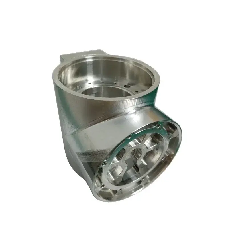
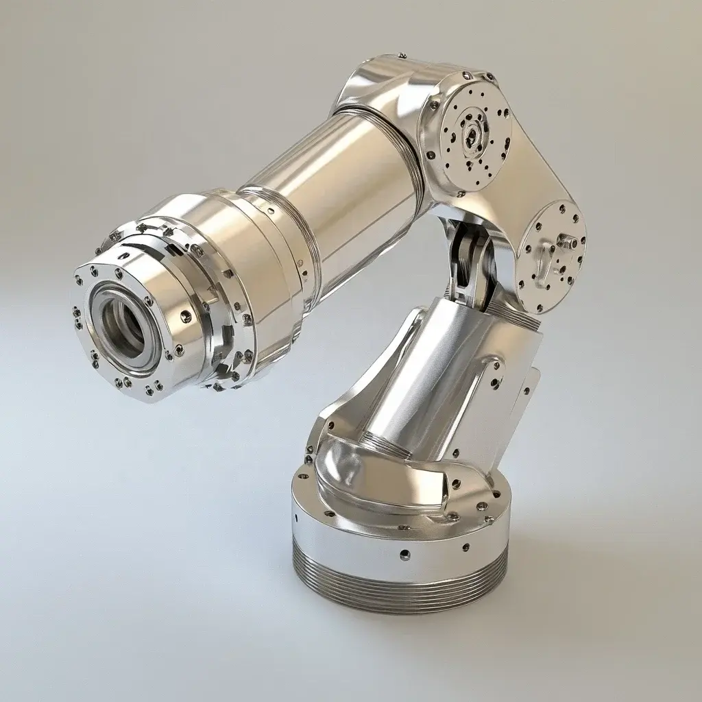
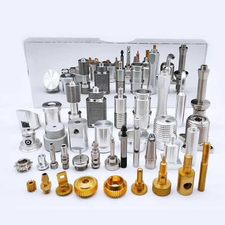
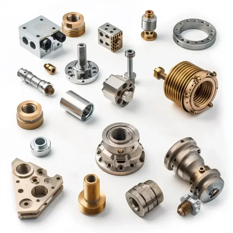
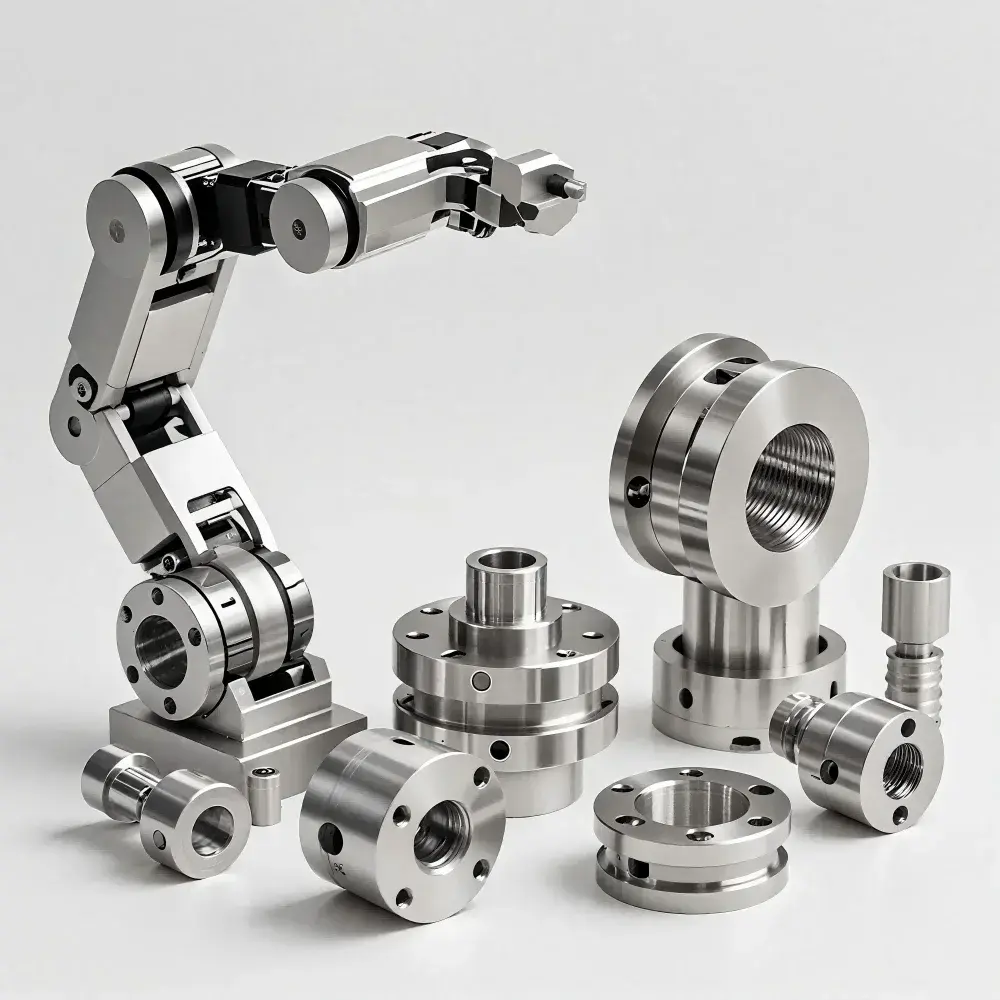
This is a professional place Five-axis CNC machining Shine, then Greglight CNC Be your expert partner. As a leader in advanced manufacturing, we focus on solving complex metal parts manufacturing challenges with unrivalled accuracy:
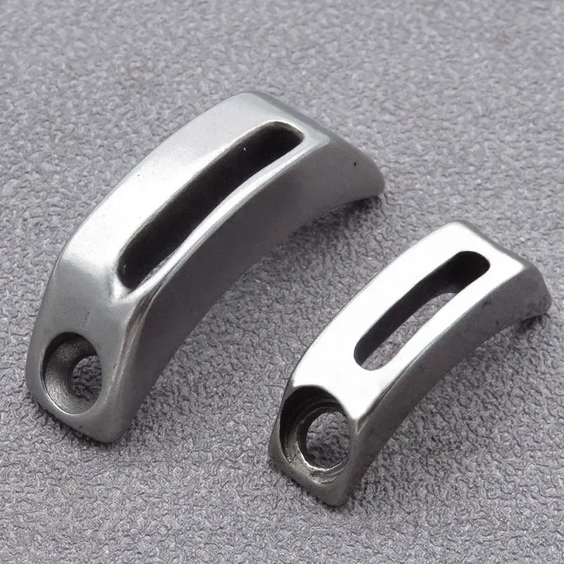
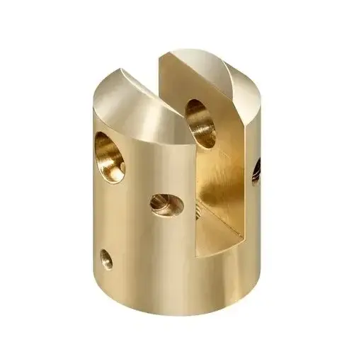
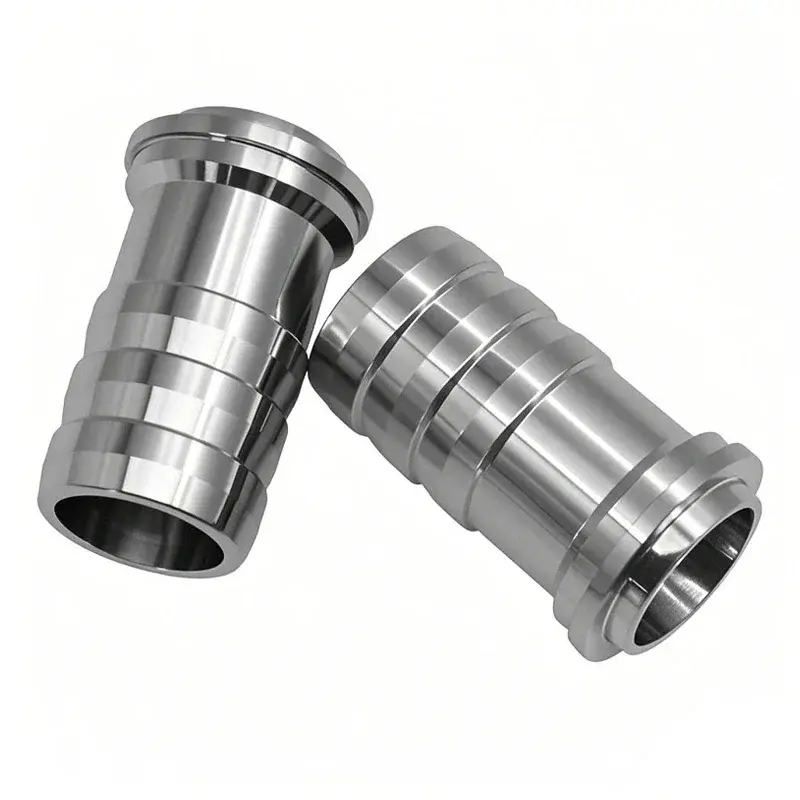
- The most advanced 5-axis technology: Our advanced CNC machines operate parts and tools along five axes simultaneously. This unlocks the ability of highly complex geometric shapes (organic shapes, deep cavity, undercut) in a single setup, ensuring unparalleled accuracy and surface quality.
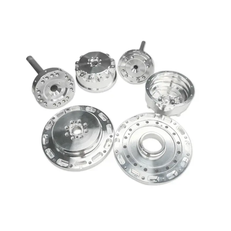
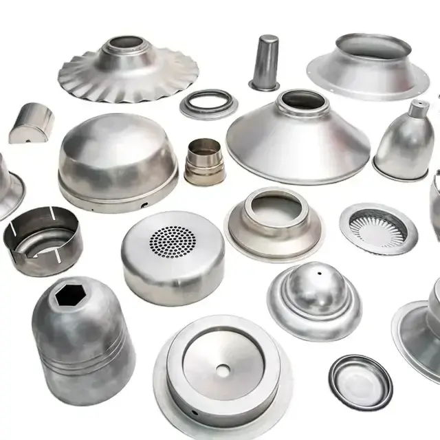
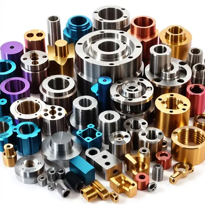
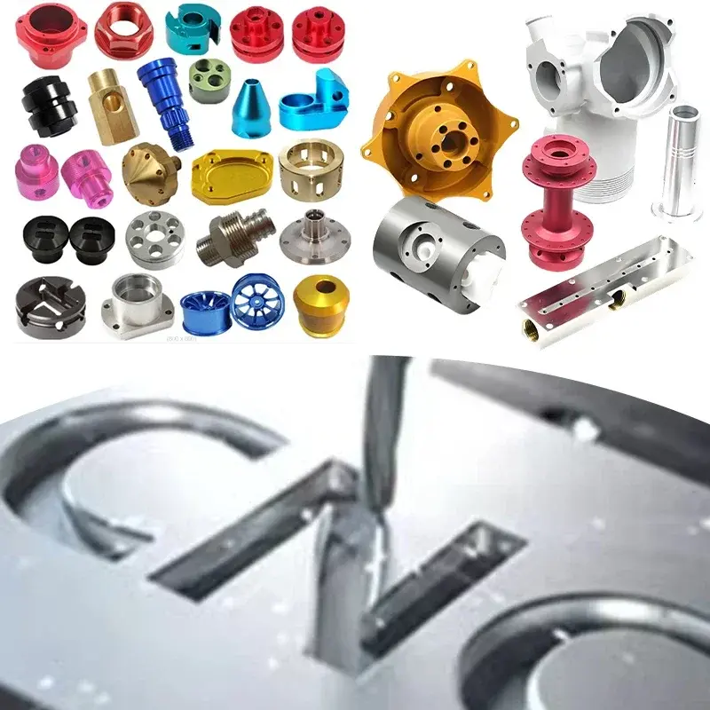
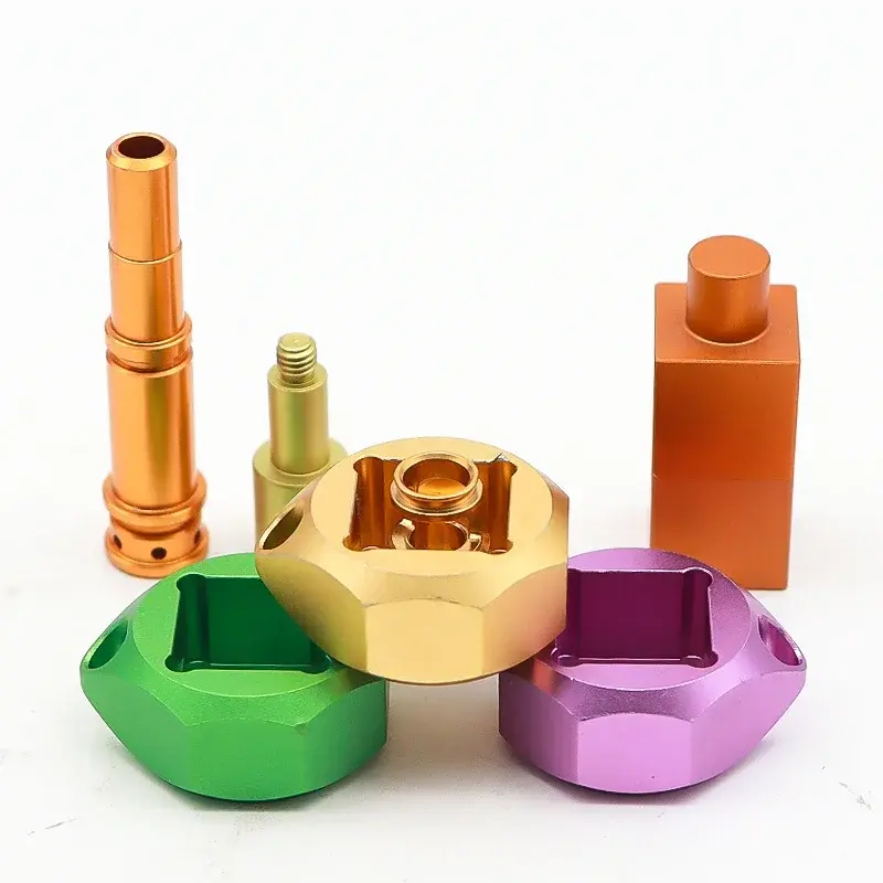
- Multi-material proficiency: Beyond FR4. We have skillfully processed a variety of metals (aluminum, steel, titanium, copper alloys, etc.), engineering plastics, composites and ceramics with optimized tool paths and parameters.
- Excellent prototype and production: Whether you need a fast prototype or a low to medium production run, Greatlight offers excellent accuracy, consistency, and quality control.
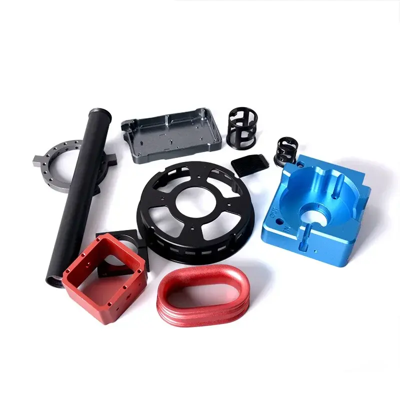
- Engineering solutions for tough challenges: Our expertise solves the requirements of production barriers: critical tolerances (±0.01mm or more), complex functions requiring complex tool access, demanding material properties and professional finishes.
- One-stop completion: We simplify your process by providing a comprehensive post-treatment: precise grinding, turning, EDM, heat treatment, anodizing, electroplating, painting, painting, powder coating and custom packaging.
DIY CNC PCB milling allows you to iterate quickly. However, when your project requires advanced materials, extreme accuracy, complex geometry, or production reliability, Greglight CNC machining. We transform the power of professional five-axis technology and deep engineering expertise to transform the most challenging design into reality with speed and accuracy.
Customize your precision parts now at the best prices! Experience Gremight Advantage.
in conclusion
CNC PCB milling is a transformative technology for electronic creators that bridges the gap between digital design and physical boards through traditional manufacturing methods and fails to achieve control. While mastering the machining of homemade copper involves careful settings, tool selection and parameter adjustment, the reward is unparalleled rapid prototyping capabilities. Understanding the limits of DIY milling, especially about ultra-high density, complex industrial materials and complex 3D components – is equally important. For projects that go beyond these boundaries, specialized five-axis CNC machining services such as Greatlight (Greatlight) offer advanced features, material expertise and precise manufacturing rigor to bring exquisite designs to life. Whether you are etching a simple breakthrough board on a desktop or machining complex aerospace components, understanding the capabilities of each stage unlocks faster innovation cycles.
Frequently Asked Questions on CNC PCB Milling (FAQ)
-
Q: How much does it cost to start milling with DIY CNC PCB?
- one: The starting price for entry-level desktop CNC machines (such as the 3018 version) starts around $200-400. You also need at least one good V bit ($15-$30), flat end mill ($10-$20 normal size), copper plate board, and possibly separate spindle upgrades or rigid frame modifications. Budget $500-$1000 for functional beginner setup. Dedicated PCB factory prices range from $3,000 to $10,000+.
-
Q: What is the minimum trace/space width that I can reliably mill?
- one: Carefully set and sharp V-position (e.g., 30° position with a 0.1mm tip) to achieve 0.2mm -0.3mm (8mil -12mil) Through practice, trace width and spacing are very achievable. Due to vibration, tool deflection and material inconsistent, making it below 0.2mm more challenging.
-
Q: Can I effectively mill a double-sided PCB with a DIY machine?
- A: Yes, absolutely! This is a major advantage. The key is:
- Specify accurate trust (registration mark) Both PCB design software side.
- Fixed plate Perfect Flat and safe.
- Mill one side and then carefully flip the board while ensuring its exact position and place it perfectly on the debris board.
- During cam processing, the Gerber layer at the top and bottom is accurately aligned using reference materials.
- Flip and browse the Z-Zero again.
- A: Yes, absolutely! This is a major advantage. The key is:
-
Q: How long does the CNC PCB milling position last?
- one: If used correctly (correct feed/speed/DOC), you can use carbide Vt-lits, but FR4 is very abrasive. Signs of wear include increased burrs, effective reduction of depth reduction, poor isolation, and tip wear visible at magnification. It is expected that V-PIT can last from 10 to 50 plates depending on complexity, material (some laminates are harder) and cutting parameters. Small sub-1MM terminal mills are more fragile and easily broken.
- Q: Why should I consider Greatlight CNC instead of sticking with more complex parts?
- one: DIY milling is excellent with fast 2D FR4 prototyping. Greglight’s 5-axis CNC feature unlocks the requirements of the solution: Beyond that:
- Advanced Materials: Precise processing of high-performance metals, alloys, plastics and composites.
- Micro: Achieving ultra-tight tolerances (±0.01mm or less), surface surfaces are DIY that cannot be achieved.
- Complex 3D geometry: Manufacture parts that require undercut, deep cavity, organic shapes and composite angles – it is impossible to use 3-axis milling.
- High-quality plated features: Reliable production of precision plate holes, cavity and surfaces requires structural integrity or electrical properties.
- Production and consistency: Ensure the same quality of parts beyond the batches of prototypes.
- Project support: Access DFM’s expertise (for manufacturing design) and material selection for demanding applications. Greatlight offers professional-grade manufacturing capabilities when your project needs what a hobby tool can offer.
- one: DIY milling is excellent with fast 2D FR4 prototyping. Greglight’s 5-axis CNC feature unlocks the requirements of the solution: Beyond that: