The main processing methods for threads in metal machining include turning, milling, tapping, etc. Today, the editor brought important technical knowledge about thread turning, the most common method in production, and shared it with you.
1
Important basic knowledge of thread processing
01. Definition of terms


①Tooth base ②Tooth side ③Tooth top photo
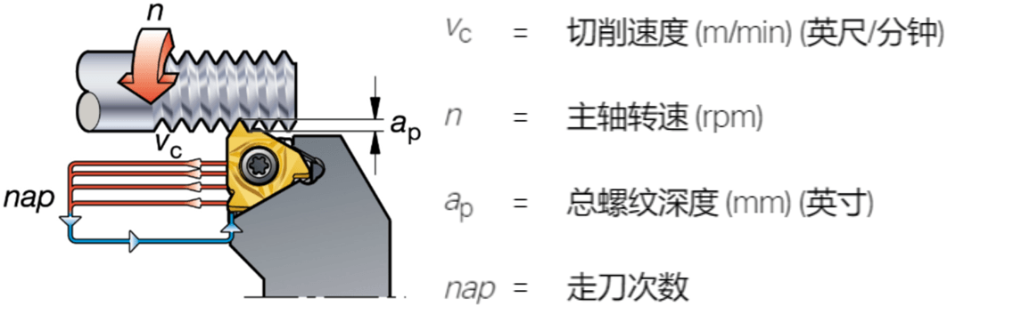
Spiral angle:
The helix angle depends on the thread diameter and pitch.
Adjust the clearance angle of the blade sides by changing the blade shim.
The angle of inclination of the edge is γ. The most common edge angle is 1°, which corresponds to a standard shim in the tool holder.

Cutting forces when entering and exiting the thread:
The highest axial cutting forces during the threading operation occur when the cutting tool enters and exits the workpiece.
Cutting parameters that are too high can cause clamped inserts to move unreliably.

Tilt the blade for clearance:
The edge angle can be adjusted using a wedge under the blade in the holder. Refer to the tool catalog table to choose which shim to use. All tool holders come with standard tool blocks with edge angle set to 1°.

Select the tool wedge based on the edge tilt angle. The diameter and pitch of the part will affect the edge angle. As shown in the picture below, the workpiece diameter is 40mm, the pitch is 6mm, and the required tool wedge should have a tilt angle of 3° (standard tool wedges cannot be used).

Markings of threaded inserts and shims:

Thread shapes and their applications:

2
Types of threaded inserts and clamping solutions
01. Multi-tooth blade

advantage:
Reduce the number of streams
very high productivity
default:
Need stable clamping
Sufficient shrinkage space is required after wire processing.
02. Full profile blade

advantage:
Better control of wire shape
Less burrs
default:
One type of insert can only cut one type of pitch
03. V-shaped blade

advantage:
Flexibility, the same insert can be used to process several steps.
default:
This will cause burrs to form which will need to be removed.
i-LOCK clamping solution:
Extremely rigid thread with fixed position inserts
Guided by the guide rail, the blade is positioned in the correct position
The screw pushes the insert back onto the guide to the radial stop at one of the contact surfaces (red contact surface) in the insert holder.
Reliable insert interface ensures longer tool life and superior thread quality

Different knife handles:

3
3 different types of feeding methods
The cutting method can have a significant impact on the threading process. This affects: cutting control, insert wear, thread quality, tool life.
01. Improved side feed
Most CNC machines can use this approach via cycle programs:
Chips compared to traditional turning types: easier to shape and guide
Axial cutting forces reduce the risk of vibration
The chip is thick but only contacts one side of the insert
Less heat transferred to the blade
First choice for most threading operations

02. Radial feed
Most common method – the only method older non-CNC lathes can use:
Produces hard “V” shaped chips
Even blade wear
Insert seats are exposed to high temperatures, limiting entry depth
Suitable for processing fine wires
Possible vibration and poor chip control when machining coarse threads
First choice for work hardened materials

03. Alternative diet
Recommended for large teeth
Uniform insert wear and maximum tool life when machining very large pitch threads
The chips are guided in two directions, making them difficult to control

4
Ways to Improve Machining Results

Cutting depth decreases layer by layer (left) and cutting depth is constant (right)
01. Cutting depth decreases layer by layer (chip surface remains unchanged)
Capable of achieving a constant chip area, this is the most commonly used method in CNC programs.
The first passage is the deepest
Follow the recommended values on the catalog power chart
A more “balanced” flea area
The last tool pass is actually about 0.07mm
02. Constant cutting depth
Regardless of the number of passes, the depth of each pass is the same.
Have higher requirements for blades
Guarantee optimal chip control
It should not be used when the pitch is greater than TP1.5mm or 16TP
Use extra margin to finish the crest of the wire:
Instead of turning the blank to the exact diameter before machining the thread, use the allowance/additional material to refine the crest of the thread. For finishing ridge inserts, 0.03 – 0.07 mm of material should be left from the previous turning process to allow the ridge to be properly formed.

Recommended feed value for external threads (ISO metric):

Make sure the workpiece and tool are aligned:
Use a maximum centerline deviation of ±0.1 mm. If the cutting edge position is too high, the clearance angle will be reduced and the cutting edge will be scratched (broken); if the cutting edge position is too low, the thread profile may be incorrect;

5
Thread Turning Application Tips for Success

1) Before threading, check whether the workpiece diameter has the correct machining allowance and add 0.14mm as peak allowance.
2) Precisely position the tool in the machine tool.
3) Check the adjustment of the cutting edge in relation to the original diameter.
4) Make sure you are using the correct insert geometry (A, F or C).
5) Ensure sufficiently large and uniform clearance by selecting the appropriate shim (insert-tilt shim) to obtain the correct sidewall clearance.
6) If the thread is not qualified, check the entire tightening including the machine tool.
7) Check available CNC programs for thread turning.
8) Optimize feeding method, number of passes and size.
9) Ensure correct cutting speed to meet application requirements.
10) If the thread pitch of the workpiece is incorrect, check whether the pitch of the machine tool is correct.
11) Before cutting the part, it is recommended to start the tool at a minimum distance of 3 times the pitch.
12) High precision coolant can extend tool life and improve chip control.
13) The quick change system ensures quick and easy tightening.
When selecting tools for thread turning operations, you should consider:
Check overhangs and any required clearances (e.g. shoulders, counter spindle, etc.)
Minimize tool overhang for quick setup
For less rigid clamping, choose an insert with a lower cutting force
High-precision coolant extends tool life and improves cutting control
Easily connect coolant with plug-and-play coolant connections
In order to ensure productivity and tool life, multi-tooth blades are the first choice, single-edged full-tooth blades are the second choice, and V-tooth blades are the choice with the lowest productivity and shortest tool life.
Blade wear and tool life:
Feeding method, optimize the feeding method, number of passes and depth;
Tilt the blade to ensure a sufficiently large and uniform gap (blade tilt block);
Insert geometry, make sure you use the correct insert geometry (geometry A, F or C);
Blade material, choose the correct material according to the material and toughness requirements;
Cutting settings, change cutting speed and number of passes if necessary.
Daguang focuses on providing solutions such as precision CNC machining services (3-axis, 4-axis, 5-axis machining), CNC milling, 3D printing and rapid prototyping services.