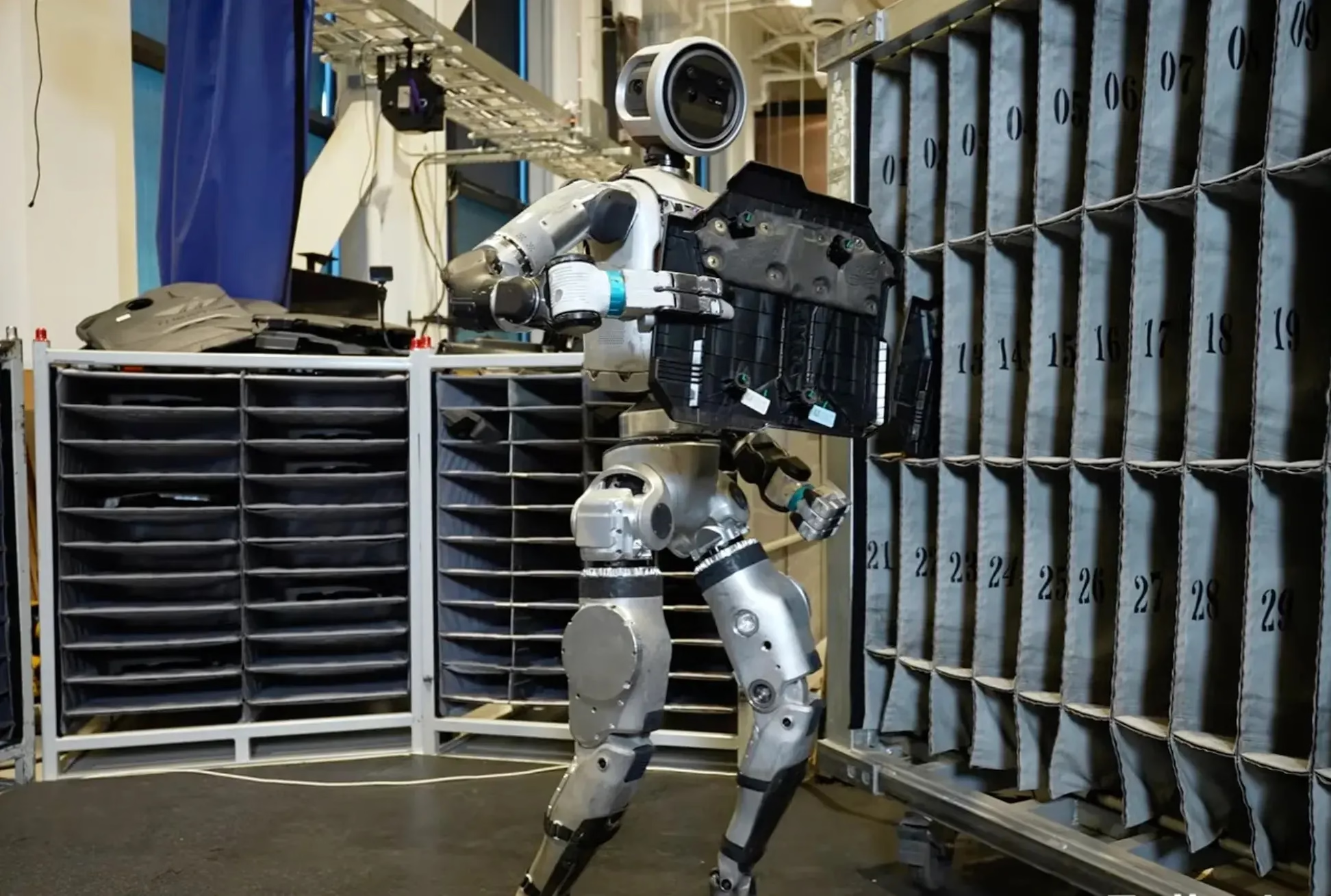
Legs that wander on the same path
If the hip and knee bores run out of position, the controller keeps correcting. The robot drifts left, the battery drains faster, and the operator blames the software. Bore-to-bore position error is the real cause.
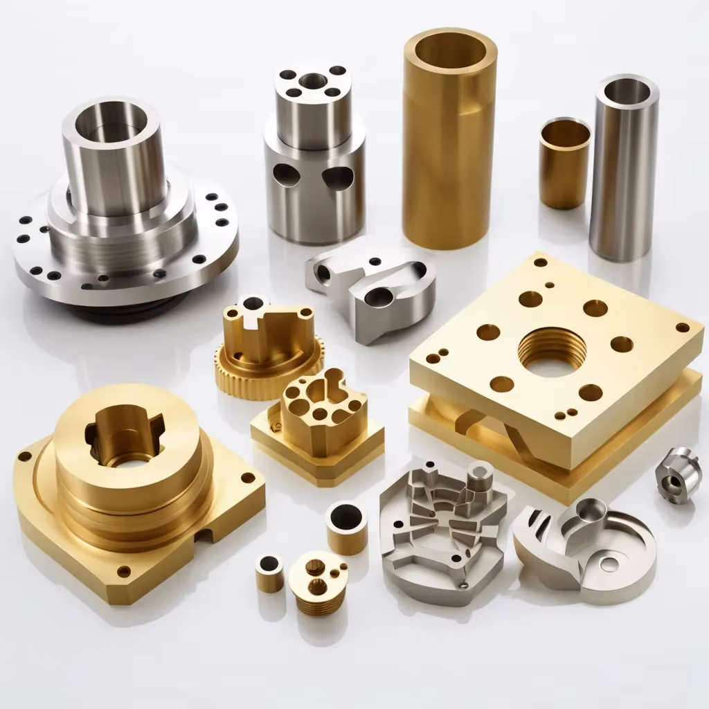
We machine the structural and joint parts that keep a quadruped stable: hip housings, knee brackets, leg tubes and sensor mounts. Tolerances held to ±0.005 mm, DFM feedback in 12 hours.

Most failures on a Spot-class platform trace back to one of these four.
If the hip and knee bores run out of position, the controller keeps correcting. The robot drifts left, the battery drains faster, and the operator blames the software. Bore-to-bore position error is the real cause.
A bearing seat that is slightly oval, or a shoulder face not square to the bore, lets the bearing creep. Play shows up as a click at each step. By then the leg assembly is already in the field.
Thin walls and sharp internal corners concentrate stress. The part passes inspection, then cracks near a motor mount after a few hundred walking cycles. Wall thickness and corner radii are the fix.
Anodic buildup on a tight sensor mount changes the fit by a few microns. Cameras tilt, calibration drifts, and the perception stack reports bad depth. Masking or post-machining the seat solves it.
One setup family, one inspection plan, one traceable program per part.

Hip and knee housings carry bores on more than one face. Every time a part is moved to a new fixture, the datum shifts a little. On a quadruped that shows up as a leg that will not track straight.
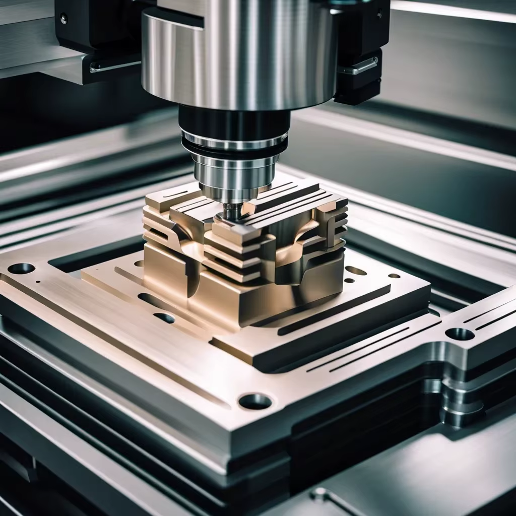
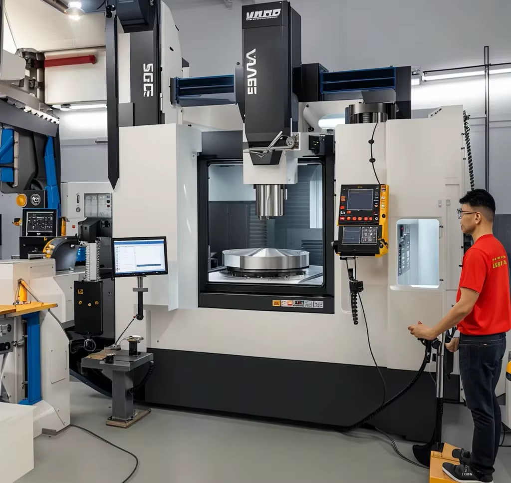
We cut the bearing bores, the shoulder faces and the motor mount pads in a single 5-axis cycle on a Ø400 mm rotary table. Datum stays referenced to one face, so the bore-to-bore relationship is set by the machine, not by a second op. Where the geometry allows, we bore and turn the same part complete to avoid a re-chuck.

A Spot-class leg is a mass problem. Every gram at the foot costs torque at the hip, and torque costs battery. 7075 aluminum gives a better stiffness-to-weight ratio than 6061 for leg tubes and brackets, but it machines differently and tends to move after roughing.
We rough, stress-relieve, then finish. For parts that see repeated impact at the foot, 17-4PH stainless or Ti-6Al-4V is the better call, with the trade-off of higher mass and longer cycle time. Titanium needs sharp tooling and slow passes; it is not a material to choose casually.
Match the wear mode to the material, not the other way around.
| Part family | Typical material | Finish |
|---|---|---|
| Hip and knee housings | 7075-T6 aluminum | Hardcoat anodizing |
| Leg tubes and links | 6061-T6 aluminum | Clear anodizing |
| Foot contact pads | 17-4PH stainless | Bead blast |
| Sensor and camera mounts | 6082 aluminum | Black anodizing |
| High-load pins and bushings | Ti-6Al-4V, 440C | Polished |
| Insulating shims | PEEK | As machined |
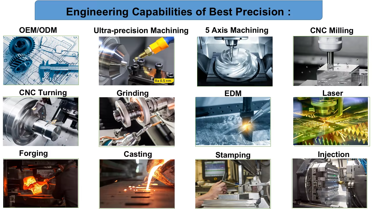
Six processes cover the full robot, from frame to foot.
Housings and brackets finished in one setup. 16 simultaneous 5-axis centers, up to 4,000 mm travel.
Leg tubes, panels and plates with repeated features. 12 four-axis mills and 27 three-axis machines.
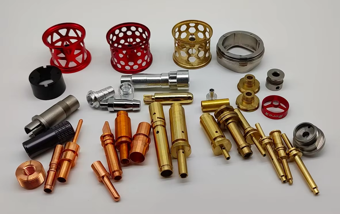
Pins, shafts and bushings turned and milled without a second chuck. 16 mill-turn centers.
One-off leg links and mounts for fit checks before tooling. No minimum order quantity.
Anodizing, plating, bead blasting and laser marking with 1.5 mm minimum character height.
Body shells, covers and larger housings when milling is not the economical route.
Numbers from the floor, not from a brochure.
| Item | Value |
|---|---|
| Achievable tolerance | ±0.005 mm |
| Fine surface finish | Ra 0.2–0.8 μm |
| Standard finish | Ra 0.8–1.6 μm |
| Maximum part size | 4,000 mm |
| Largest travel | 4,000 × 400 × 150 mm |
| Rotary table | Ø400 mm |
| Minimum order | One part |
| Shipping | 3–5 days |
Founded 2011. Three wholly-owned plants, 7,600 m², 150 technicians.
Fifteen years of metal cutting, most of it short-run and prototype work for robotics, medical and automotive teams.
Millimeters, not a best-case lab figure. Verified on the CMM and reported on request.
Send a STEP file and we return pricing plus a DFM note within 12 hours. Production can start within 24 hours.
Sixteen simultaneous 5-axis centers, twelve four-axis mills, sixteen mill-turn centers and more.
One prototype or a 10,000-part run. The setup does not change; only the batch does.
That is the share of orders that missed their date. We track it because customers ask.

Joint housings and leg links that keep repeatability after thousands of cycles.

Sensor and camera mounts machined flat so optics stay aligned through vibration.

Lightweight 7075 frames and titanium pins where mass budget is tight.

Single-unit parts for design iterations, before any tooling is committed.
We machine both. Individual housings, brackets, tubes and pins are routine. For a full leg, we machine each part to its own drawing and hold the mating features to a common datum so the assembly stacks up correctly.
If you send an assembly STEP file, we will flag which features drive the fit and quote those at tighter tolerance. The rest can run looser and cost less.
±0.005 mm is achievable on critical bores and mounting faces, verified with in-process probing and CMM inspection. On a multi-face housing, the harder number is not the diameter but the position of one bore relative to another.
We handle that by cutting all critical features in one 5-axis setup. If your drawing calls for a tighter relationship than the process can hold, we will say so during DFM review rather than after the parts ship.
6061-T6 is the default for general links and brackets. It machines cleanly, takes anodizing well and is predictable.
7075-T6 is worth the extra cost when stiffness per gram matters, which it usually does on a legged robot. It is stronger but less corrosion resistant, so specify a finish. 7075 also moves more after roughing, so we rough, stress-relieve and finish rather than cutting to size in one pass.
Anodic coatings build up on the surface, typically a few microns per side depending on the type. On a slip fit or a bearing seat, that is enough to matter.
We mask critical bores before anodizing, or leave stock and machine the seat after coating. Tell us which features are fits and which are cosmetic, and we will mask accordingly.
Yes. We sign an NDA on request before any file transfer. Uploads are handled as confidential and are not shared outside the project team.
If your program requires it, we can also restrict which engineers see the data. Our facility holds ISO 27001:2022 for information security management.
One part. There is no minimum order quantity. A single prototype and a 10,000-part run go through the same quoting and inspection process.
Unit price drops as quantity rises because setup is amortized, but we do not refuse a one-off. Most robotics programs start at one or two units for a fit check.
Quotation and a free DFM analysis come back within 12 hours of receiving a usable CAD file. Production can start within 24 hours of approval.
Standard parts ship in 3–5 days. Complex multi-setup assemblies take longer, and we will give you the real date at quote rather than a date you want to hear.
Every order gets raw material verification, in-process monitoring and a final inspection before shipment. We inspect 100% of parts, not a sample.
Inspection reports are available on request, including CMM data for critical features. If your quality system needs a specific report format or a first-article report, tell us at the quoting stage so we build it into the plan.
Upload a STEP or IGES file and we will return pricing plus a DFM note within 12 hours. No minimum order quantity, no obligation.
12-hour quote100% inspectionNo MOQNDA on request
Trusted by engineers and manufacturers worldwide
Upload your 3D model or 2D drawing and get a quotation with a free DFM analysis. Maximum processing size 4,000 mm.
CNC Metals 13 grades
CNC Plastics 10 grades
Machines & processes 12 options
Surface & post-processing 10 options
Material: not selected Machine: not selected Post-process: not selected