1
Causes of workpiece deformation during wire cutting processing
If you split a piece of bamboo down the middle, both halves of the piece of bamboo will become curved, with the larger half being less curved and the smaller half being more curved. This means that the material itself will be subject to stress. The splitting process breaks the original stress balance of the material and the balance is restored by deformation. The same goes for the deformation of parts processed by wire cutting. The cutting process disrupts the original stress balance of the part.
The size of the deformation during wire cutting processing is related to the structure of the workpiece. Concave molds and punching molds with narrow and long shapes are prone to deformation, and the extent of deformation is related to the complexity of the shape, aspect ratio, etc., thin-walled parts are prone to deformation.
If the deformation is very small, within the precision range required for processing, this deformation can be almost ignored. However, if the deformation exceeds the machining accuracy requirements, large size deviations will occur, affecting the machining shape of the workpiece.
There are many reasons for deformation, such as material problems, heat treatment problems, structural design problems, process layout problems, workpiece clamping problems and cutting path selection problems when from cutting to wire, etc. These different reasons will lead to deformations due to the internal constraints of the material.
Effect of thermal stress on the shape of the part
2
Preventive measures against deformation of parts during processing
Certain measures can be taken to control deformation during wire cutting processing and prevent deformation from occurring.
1) Rough machining or cutting with stress relief before cutting
If a large area of material must be cut, the relative residual stress balance within the material will be destroyed and the material will experience large deformation. We can first remove most of the stress in the material by roughing it out (rough machining) and removing most of the margin first, or cutting a path to release the stress.
For wire EDM processing of large concave molds, two main cuts can be made. First, increase the offset of the main cut by 0.1-0.2mm on one side for the first main cut to allow the stress to be released, then use the standard. Offset the second main cut, as shown in the image below.
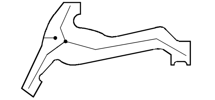
Perform rough machining without constraint to reduce deformation
For long and narrow shapes, first cut the stress relief path inside the hole, and then process the hole shape, as shown in the figure below.
anti-stress cup
2) Thread hole processing
When cutting the punch, if the punch hole is not processed and the punch is cut directly from the outside of the material, as shown in figure (a) below, deformation will occur due to ‘an unbalanced stress in the material, resulting in an opening or closed deformation. Wire holes can be machined on the material to perform closed contour processing, as shown in Figure (b) below, which can greatly reduce the deformation caused by wire EDM processing.
(a) Large deformation (b) Small deformation
Treatment of wire holes to reduce deformation
3) Optimize processing paths
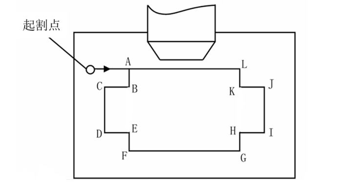
In general, it is best to arrange the processing start point near the clamping end, arrange the cutting section that separates the workpiece from its clamping portion at the end of the processing path, and set the point break near the clamp end of the blank. In some processes, unreasonable arrangements of the processing path also cause deformation of the cutting wire. As shown in the figure below, the most reasonable processing path is: A→B→C→D…→A. If you follow clockwise direction: A→L→K→J…→A, since the workpiece is cut from the clamping part at the beginning of cutting, when the processing reaches the end of the program, The cutting precision of the punch is directly affected by the unreliable influence of the clamping factor.
Layout of processing paths
4) Multiple cuts
Some parts still have some deformation after taking certain measurements. In order to meet the precision requirements of the workpiece, the traditional habit of cutting to size at one time can be changed and the method of multiple cuts can be used. Rapid wire cutting uses multiple cutting methods, mainly to achieve better surface roughness, but the use of multiple cutting methods has very important practical significance to reduce the deformation of mold parts caused by stress problems.
5) Optimization of multi-hole concave pattern processing technology
When the jig is processed by wire cutting, due to the effect of the original internal stress and the influence of thermal stress generated by wire cutting, non-directional and irregular deformation will occur, making the jig The subsequent cutting thickness is uneven and affects the processing quality. .and the precision of the processing.
In response to this situation, models that require relatively high precision are cut and processed multiple times. When cutting for the first time, the waste from all the molded holes is cut off. After removing the scrap, the automatic moving function of the machine tool is used to complete the cutting and cutting of the molded holes in sequence: main cavity cutting a, scrap taking → main cavity cutting b, taking scrap → Mainly cut cavity c, take scrap →…… → Mainly cut cavity n, take scrap → Cut cavity a → Cut cavity b → … → Cut the n cavity and the treatment is completed.
This cutting method allows each hole enough time to release internal stress after processing, can minimize the mutual influence and trace the deformation of each hole due to different processing sequences, and better guarantee the processing size of the model.
However, this method requires more wire threading time and greater workload, so it is more suitable for slow wire cutting machine tools with automatic wire threading mechanisms. After cutting in this way, after measurement, the shape and size meet high precision requirements.
6) Set the amount of multi-segment buffering
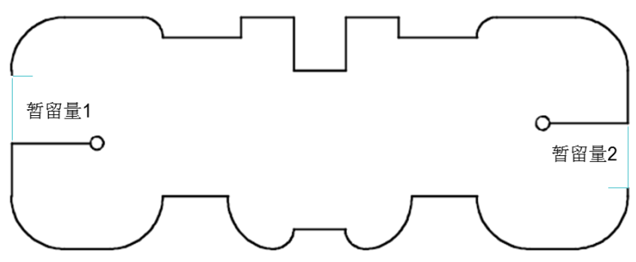
For processing large and complex-shaped parts, two or more temporary tolerances should be set and multiple starting cutting points should be set, as shown in the figure below. When programming, open forms are used for processing. Before programming, the graphics are broken into several segments and connected in series. During processing, the contour is processed first and the temporary part is processed last.
Set multi-segment retention capacity
Daguang focuses on providing solutions such as precision CNC machining services (3-axis, 4-axis, 5-axis machining), CNC milling, 3D printing and rapid prototyping services.


