
Wheelchair Brake Lever Machining
A brake lever is a safety interface, not a bracket. This page explains how material, pivot geometry, surface finish and burr control decide whether the lever still releases cleanly after 50,000 cycles, and what to check before you release a print for production.
In this article
- 1
- 2
- 3
- 4
- 5
- 6
- 7
Why wheelchair brake lever machining is not standard hardware work
Most machined parts fail because of a dimension. A brake lever fails because of a feel. The user pulls it hundreds of times a day with limited hand strength, often with cold or wet hands, sometimes with one arm only. If the lever binds, the wheelchair does not stop when the user expects it to. That is the whole design problem in one sentence.
So the print carries two kinds of requirements. Functional ones: pivot bore diameter, lever arm length, cable or linkage anchor position, spring seat depth, stop face angle. And perceptual ones: how smooth the lever body feels, whether the pivot returns without a catch, whether the release edge cuts into a palm. The second group is not on the drawing, but it is what the end user notices.
This is where wheelchair brake lever machining differs from general CNC work. A ±0.005 mm bore is only useful if it solves a real binding problem. A mirror finish on the wrong face does nothing for safety and adds cost. Engineers who understand which features carry the load, and which are cosmetic, get better parts at lower cost.
- 1Load pathThe pivot bore and the cable anchor take almost all the stress.
- 2Wear pathThe stop face and the ratchet or detent teeth wear first.
- 3Touch pathThe palm face and release edge decide perceived quality.
Material choice and what it does to the cut
Aluminum 6061-T6 and 7075 dominate lever bodies. 6061 machines fast, anodizes cleanly and holds a ±0.005 mm bore without drama, which makes it the default for levers that will not see heavy abuse. 7075 gives roughly double the yield strength, so you can thin the lever arm and keep stiffness. It cuts slower, and the chips are abrasive on tool edges.
Stainless 304 and 316 appear wherever the device is cleaned often. Think rehab clinics, shared equipment, any environment with alcohol wipes and disinfectant spray. 316 and 316L resist chloride pitting far better than 304, but they work-harden fast. Feed too light and the tool rubs instead of cutting, which pushes hardness up at the surface and shortens tool life. 17-4PH is the middle path when you need corrosion resistance plus strength, and it can be aged after machining.
POM and glass-filled PA show up on low-load levers and on covers. They are quiet, light, and cheap to mold, but they creep under sustained spring load. If a plastic lever sits under a compressed spring for two years in a warehouse, the stop face can deform. For any part that must hold position passively, metal is the safer answer.
- 16061-T6Default for lever bodies and pivot blocks. Fast to cut, easy to anodize.
- 27075-T6Use when the arm must be thin or the load is high. Slower cutting.
- 3316 / 316LBest corrosion resistance. Watch work hardening on light finishing passes.
- 417-4PHStrength plus corrosion resistance. Age after machining.
Pivot bore, arm length and the geometry the user actually feels
The pivot bore sets the whole lever. A common design runs a Ø6 mm to Ø8 mm bore on a 20 mm to 60 mm arm, which gives a mechanical advantage of roughly 3:1 in the user's favor. Bore tolerance of H7 (about +0.012 mm on Ø6 mm) is usually enough for a bushing fit. Going tighter than that buys nothing and makes assembly harder.
Perpendicularity between the bore axis and the mounting face matters more than bore diameter. If the bore tilts by 0.05 mm over a 10 mm depth, the lever cocks in the housing and drags on one side. The user feels a rough pull, and the return spring has to fight the drag. This is a classic case where a generous diameter tolerance with a tight geometric tolerance outperforms the reverse.
Arm length and anchor position are tolerance-sensitive because they set cable travel. A 1 mm error in anchor position changes cable pull by roughly 1 mm at the same lever travel. On a brake that needs 15 mm of cable movement to lock the wheel, that is a 6 to 7 percent error. Not fatal, but enough to make the brake feel either mushy or grabby. Hold anchor position to ±0.1 mm and you will not notice it.
Surface finish and burr control on a safety part
Finish requirements split by function. Bearing surfaces such as the pivot bore and bushing journal want Ra 0.8–1.6 μm so the lever slides without galling. Palm contact faces feel better at Ra 0.8–1.6 μm after bead blasting or tumbling; a polished surface on a grip area actually feels slippery when wet, which is worse for the user. Non-critical internal faces can stay at Ra 1.6–3.2 μm as machined.
Burs are the real hazard. A burr on the pivot bore edge acts like a file on the bushing and slowly enlarges the bore. A burr on the cable anchor slot wears the cable jacket and can fray a strand. A burr on the release edge cuts the user's hand. None of these show up in a first-article report unless someone looks for them.
Deburring is therefore a controlled process, not a quick wipe. Hand deburring with a fine file and abrasive cord works for prototypes. Production runs need defined edges: a 0.2 mm to 0.3 mm chamfer or break on all external edges, and a radius or cross-hole deburr on internal intersections. Specify the edge condition on the drawing. If you leave it blank, you get whatever the operator decides that morning.
The same logic applies to anodizing. Hardcoat anodizing adds 25 to 50 μm of oxide and grows the part. A bore that was H7 before coating will not be H7 after. Either mask the bore, or machine it undersized to allow for growth. Type II clear anodizing at 5 to 15 μm is easier to manage but offers less wear resistance on the stop face.
- 1Bearing facesRa 0.8–1.6 μm, no visible tool marks across the sliding direction.
- 2Grip facesBead blast or tumble for texture. Avoid mirror polish.
- 3Internal edgesCross-hole deburr on all intersecting bores and slots.
- 4Coating growthAccount for 25–50 μm hardcoat on critical bores.
Process planning: which machine does which feature
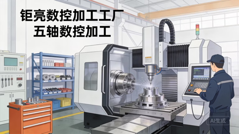
A lever body usually has three machining setups if you split operations, and one setup if you plan the fixtures well. Five-axis machining with a Ø400 mm rotary table lets you cut the pivot bore, the arm profile, the stop face and the anchor slot in a single cycle. That matters because every extra setup adds stack-up error, typically 0.02 mm to 0.05 mm per re-fixture.
For a part with a round pivot and a flat arm, mill-turn is often the better answer. Turn the pivot boss to final diameter, then mill the arm and slot without releasing the part. One setup, one datum, bore-to-face perpendicularity that you do not have to chase. Mill-turn centers handle this well when the part fits the spindle.
Downstream operations matter just as much. Tumbling removes small edge burs and softens the feel. Anodizing, plating or powder coating follow, then laser marking if the part carries a lot number or a device identification symbol. Laser marking at a minimum character height of 1.5 mm stays legible after coating and survives repeated cleaning.
- 1Single-setup goalCut bore, profile and stop face without re-fixturing.
- 2Stack-up budgetAllow 0.02–0.05 mm per extra setup.
- 3MarkingLaser mark at 1.5 mm minimum character height.
How to verify a lever before it ships
First article inspection on a brake lever should not stop at dimensions. Measure the pivot bore diameter, bore perpendicularity, anchor position and stop face angle. Then assemble the lever on a mating housing and cycle it. Twenty cycles by hand is enough to find a bad fit. If the lever binds on cycle three, no CMM report will save it.
In production, watch two things statistically. Pivot bore diameter and anchor position. These two drive fit and cable travel, and both drift when tool wear sets in. A control chart on the bore over a 500-piece run catches tool wear before it becomes a scrap batch. Other features can be checked at lower frequency.
For medical device programs, traceability closes the loop. Material certificates, heat lot numbers, machining records and inspection results should be linkable to a specific part batch. That is standard under ISO 13485:2016. Ask for a sample traceability packet before you place a production order. If the supplier cannot produce one quickly, that tells you something.
Which material and process fits which lever
Use this table to narrow the choice before you send an RFQ. Each row is a real design situation, not a generic recommendation.
| Design situation | Recommended material | Machining approach | Finish target |
|---|---|---|---|
| General mobility lever, moderate load | 6061-T6 | 3-axis mill, 2 setups | Clear anodize, Ra 0.8–1.6 μm |
| Thin arm, high stiffness needed | 7075-T6 | 5-axis, single setup | Hardcoat anodize |
| Shared equipment, daily disinfection | 316 or 316L | Mill-turn | Bead blast, passivated |
| Corrosion plus high strength | 17-4PH | 5-axis, 2 setups | Passivate, H900 age |
| High-volume, low-load lever | POM or PA-GF | CNC prototype, then mold | As machined |
| Prototype for clinical trial | 6061-T6 | 3-axis, 1 setup | Tumble deburr, as machined |
| Lever with cable anchor slot | 6061-T6 or 304 | Mill-turn plus cross-hole deburr | Anodize without masking |
| Wear-resistant stop face | 440C or 17-4PH | 4-axis, hardened after cut | Polished stop only |
The trade-off in one line
If the lever is a low-cost mobility accessory, 6061-T6 on a 3-axis mill with clear anodizing is enough and keeps cost down. If it is a medical or rehab device under repeated disinfection and clinical traceability, choose 316L or 17-4PH, single-setup mill-turn or 5-axis, controlled edge break, and a supplier who can hand you a material certificate and an inspection report without being asked twice.
Questions engineers ask before releasing the print
What bore tolerance should a wheelchair brake lever pivot use?
H7 is a good starting point for a bushing fit. On a Ø6 mm bore, that is roughly +0.012 mm, and it assembles without force while keeping play under 0.02 mm.
Going tighter than H7 rarely helps. The perpendicularity of the bore to the mounting face usually controls binding more than the diameter does.
Does anodizing change the pivot bore size?
Yes. Type II clear anodizing adds about 5 to 15 μm per surface, and hardcoat adds 25 to 50 μm. On a Ø6 mm bore, hardcoat can shrink clearance by 0.05 mm to 0.10 mm on diameter.
Either mask the bore, or machine it undersized by the coating growth before anodizing. Decide this before the first cut, not after.
How do you check for burrs on a machined lever?
Visual check under 10× magnification on all edges, plus a cotton swab test on the pivot bore and cable anchor slot. If fibers catch, there is a burr.
For production, define the edge condition on the drawing: 0.2 mm to 0.3 mm chamfer or radius on all external edges, with cross-hole deburring on internal intersections.
Can a plastic lever replace a machined metal one?
For low-load levers on folding or transport wheelchairs, yes, provided the part is not held under sustained spring load. Plastics creep, and a deformed stop face changes brake engagement over time.
Use metal wherever the lever holds position passively or where the stop face carries the braking load.
What surface finish is right for the palm contact area?
Ra 0.8–1.6 μm after bead blasting or tumbling gives grip without sharp texture. A mirror polish feels smooth in the hand but becomes slippery when wet, which is the opposite of what a user needs.
Keep polished finishes for bearing surfaces, not grip surfaces.
What documentation should come with a production batch?
Material certificate with heat lot number, inspection report covering critical dimensions, and a link between those records and the specific batch. Under ISO 13485:2016 this is expected, not optional.
Ask to see a sample traceability packet during quoting. It is a fast way to judge how the supplier actually works.
Send your lever drawing and get a manufacturability review
We review the print, flag features that will be hard to hold, and return a quotation with DFM notes within 12 hours. Uploads stay confidential, and an NDA is available on request.
Quotation within 12 hoursNo minimum order quantity100% inspection before shipment
More machining notes from the shop floor
We publish setup notes, tooling trials and inspection data from the factory floor.











