
Bulk Metal Die Casting: What Decides Part Quality at Volume
This page covers how the process actually runs at volume: alloy choice, tooling, wall thickness, draft, tolerances, and the machining steps that follow. It is written for design and sourcing engineers who need to judge whether a part should be cast, cast and machined, or machined from solid.
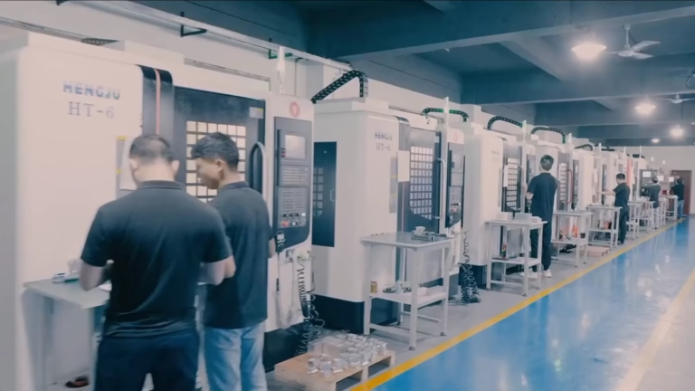
Cast First, Machine Where It Matters
A die casting tool sets the geometry. The CNC operations after it set the tolerance. Treat them as one process, not two suppliers.
How a High-Volume Run Actually Works
Hot chamber machines handle zinc and magnesium alloys because the melt can sit in the gooseneck with less oxidation. Aluminum and most of its alloys go to cold chamber machines, where a ladle pours metal into the shot sleeve and a plunger pushes it into the cavity. The choice is not a preference. It follows from how the alloy reacts to sitting in a heated chamber between shots.
Cycle time at volume is dominated by solidification, not by the pour. A 3 mm aluminum wall cools in a few seconds; a 10 mm boss under the same die takes several times longer. That single fact explains most of the cost structure in bulk metal die casting: thick sections slow the press, raise porosity risk near the center, and force longer hold times. Thin, uniform walls are cheaper to cast and easier to keep flat.
Tooling decides the rest. Cavity inserts are machined from H13 or a comparable hot work steel, then heat treated and finished. We cut critical inserts to ±0.001 mm on five-axis centers before they ever see a press, because the cavity geometry is what the part will repeat for the next several hundred thousand shots. A worn insert does not fail suddenly. It drifts, and the drift shows up as a dimensional trend on your incoming inspection reports.
Draft, radii, and parting line placement are set at the same stage. A 1° draft on an inside wall is usually enough for aluminum, but deep ribs and textured surfaces need more. Put the parting line where it does not cross a sealing face or a cosmetic surface. Fixing that after the tool is cut means welding and re-cutting the insert.
- 1Wall thicknessKeep aluminum walls between 2 mm and 4 mm where the design allows.
- 2Draft1° minimum on inside walls; 2–3° on textured or deep features.
- 3RadiiUse generous fillets at ribs and bosses; sharp internal corners crack.
- 4Parting linePlace it off sealing faces, bearing surfaces and visible cosmetic areas.
Choosing an Alloy Before Choosing a Tolerance
Aluminum alloys carry most high-volume work. ADC12 and A380 cast easily, fill thin walls, and hold up under secondary machining. They are the default when the part is a housing, a bracket, or a structural cover and weight is not the driving constraint. A360 and 383 trade a little fluidity for better corrosion behavior or pressure tightness.
Magnesium, typically AZ91D, is the choice when weight matters more than surface finish. It machines fast and casts thin walls well, but it needs care in handling and finishing. Zinc alloys like Zamak 3 and Zamak 5 cast to tighter as-cast dimensions than aluminum, take plating and chromate well, and are common in small hardware, housings and latches. They are also heavier per unit volume, which rules them out for weight-sensitive parts.
There is no alloy that wins on every axis. A380 machines cleanly but is not the best for thin cosmetic surfaces. ADC12 fills thin sections well but is a little more abrasive on tooling. AZ91D saves weight but adds process cost. The right question is which two properties matter most for the part, then accept the trade on the rest.
We keep stock in the alloys listed below and can quote alternate grades against a drawing. If the part will be anodized, tell us at the quoting stage. Not every die casting alloy anodizes to a consistent color, and the difference shows up after finishing, not before.
Common Die Casting Alloys and Where They Fit
A short selection guide for the alloys we cast most often.
| Alloy | Base | Typical Use | Note |
|---|---|---|---|
| ADC12 | Aluminum | Housings, covers, brackets | Good fluidity, fills thin walls |
| A380 | Aluminum | General purpose castings | Machines cleanly, widely available |
| A360 | Aluminum | Pressure-tight parts | Better corrosion resistance |
| AZ91D | Magnesium | Weight-sensitive housings | Lightest option, needs handling care |
| Zamak 3 | Zinc | Small hardware, latches | Tight as-cast dimensions |
| Zamak 5 | Zinc | Plated fittings | Takes plating and chromate well |
Where As-Cast Accuracy Stops and Machining Starts
A die casting tool does not produce a precision part on its own. As-cast tolerances on aluminum typically sit in the range of a few tenths of a millimeter across a feature, plus an allowance that grows with the dimension. That is fine for a mounting flange. It is not fine for a bearing bore, a seal groove, or a mating face that has to sit flat within microns.
That is why most high-volume programs combine casting with CNC finishing. The casting gives you near-net shape at low cost per part. The machining gives you the tolerance where the drawing demands it. We hold ±0.005 mm (±0.0002 in) on machined features and finish functional surfaces to Ra 0.8–1.6 μm. Cosmetic or non-critical surfaces stay as-cast.
Porosity is the other limit. Gas and shrinkage porosity form inside thick sections and at the last points to freeze. If a machined face cuts into a porous zone, you get a pinhole, a leak, or a rejected part. Two things reduce the risk: keep sections uniform, and place machining stock where the metal is dense. We review that on the DFM pass before cutting the tool.
Fixturing deserves the same attention. A casting has draft and a parting line, so it does not sit flat on a vise the way a billet does. We locate on datum features defined in the DFM review and use dedicated fixtures for repeat runs. Without that, the first fifty parts measure well and the next five thousand drift.
What to Settle Before the Tool Is Cut
Most expensive casting problems are decided on paper, months before the first shot. Whether a boss can be cast or has to be machined, whether a wall is thin enough to fill, whether a feature needs a slide in the tool: all of that is a design decision. Changing it later means re-cutting an insert, and that costs both money and weeks.
Send the 3D model and the 2D drawing with tolerances and finish callouts. We return a DFM analysis with the quotation, usually within 12 hours. It flags the features that will not fill, the walls that are too thick, the surfaces that need machining stock, and the datum scheme we would use for fixturing. You can accept it, push back, or ask for the reasoning.
Prototypes matter here too. If you need parts before the production tool exists, we can machine the geometry from solid or run a small vacuum casting batch from a silicone tool. Both let you test fit and function while the die is being cut. We hold no minimum order quantity, so a single prototype and a 10,000+ part run can sit on the same program.
Confidentiality is handled the same way at every stage. Uploads are secure and confidential, and we sign an NDA on request before drawings change hands. If your program is under one, say so at first contact so the paperwork is in place before the data moves.
Questions Engineers Ask About Die Casting at Volume
What is the smallest wall thickness you can cast?
For aluminum, 1.5 mm is possible on small features with good alloy flow, but 2–3 mm is the practical range for a stable process across a long run.
Magnesium and zinc fill thinner sections than aluminum, so those alloys can go below 1.5 mm if the geometry supports it. Send the model and we will tell you where a wall will not fill.
Can a casting hold a tight bore without machining?
No. As-cast dimensions carry variation from shrinkage, draft and die wear that a bearing bore or seal groove cannot tolerate.
We cast stock on those features and machine them to ±0.005 mm in the same program, so the part arrives at the tolerance on the drawing.
How do you deal with porosity in thick sections?
The first step is design: uniform walls, no isolated heavy masses, generous radii where metal turns.
Where a thick section is unavoidable, we adjust gate and overflow placement and may add vacuum assistance. If a machined face would cut into a porous zone, we move the machining stock or change the datum.
Do you cast and machine in the same shop?
Yes. Tooling, casting, CNC finishing, surface treatment and inspection run inside our process chain, with 127 high-precision CNC machines across the plants.
That matters for tolerance because the datum used for machining is set against the actual casting, not against a drawing assumption.
What surface finishes can follow a casting?
Anodizing in clear, color, hardcoat or conductive versions; electroless nickel and zinc plating; powder coating and black oxide; and bead blasting, tumbling, brushing or polishing.
Laser marking is available with a minimum character height of 1.5 mm. Tell us the finish at quoting, because it can change the alloy choice.
How fast can you quote and start?
Quotation and a free DFM analysis come back within 12 hours. Production can start within 24 hours once the tool and process are approved.
Parts ship in 3–5 days for machining programs. For die casting, the tool build is the long pole, so ask for the tool schedule with the quote.
Send the Drawing, Get a DFM Review Back
Upload your model and tolerances. We return a quotation with a DFM analysis within 12 hours, and flag what will cast cleanly and what needs machining.
12-hour quoteDFM includedNDA on request100% inspection









