
Custom Chinese Metal Die Casting Solution: How the Process Actually Works
This page explains what a custom chinese metal die casting solution contains, from die design to machining and finishing, and when high-pressure die casting is the right process for a part. Written for design and process engineers who need to judge a quote.
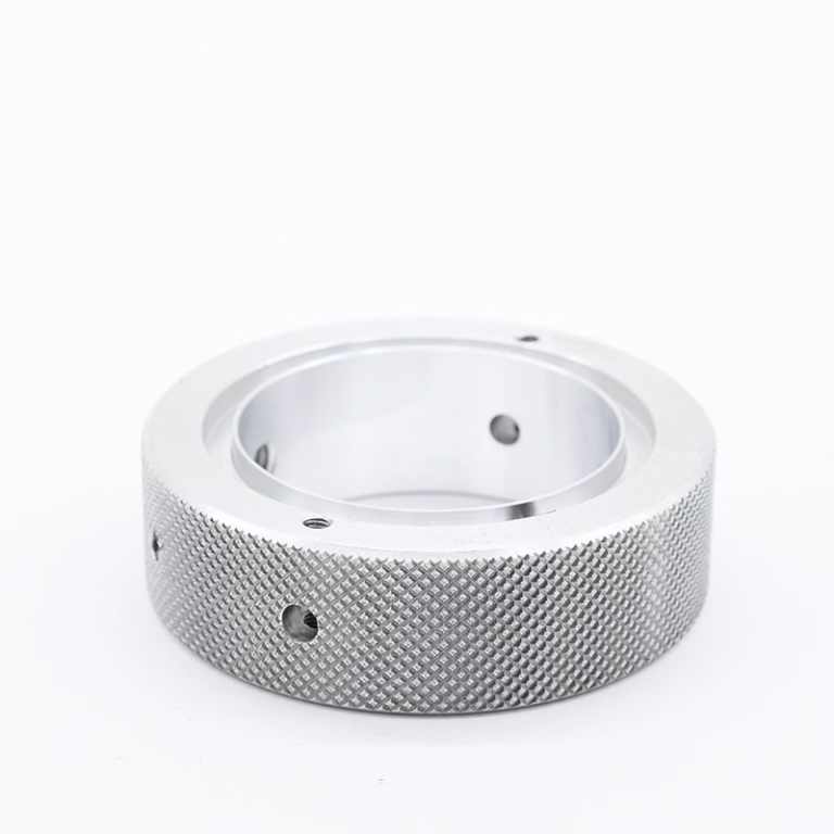
What a Custom Metal Die Casting Solution Contains
A custom chinese metal die casting solution is a chain of decisions, not one operation. Molten alloy is forced into a hardened steel die at high pressure, the part cools and shrinks, then it is trimmed, machined, finished, and measured. Each link sets limits on the next. The die decides where the parting line sits. The parting line decides where you can hold a datum. The datum decides how the part is fixtured for CNC work.
Common alloys are aluminum ADC12 and A380, zinc Zamak, and magnesium AZ91D. Aluminum dominates housings, brackets, and thermal parts. Zinc holds tighter as-cast detail and plates well, so it suits small hardware and decorative covers. Magnesium is the lightest option but needs tighter process control and careful handling.
The reason to buy this as one solution rather than four purchase orders is tolerance stack-up. Every handoff between a caster, a machinist, and a plater adds a new setup, a new datum, and a new place for a dimension to drift. When one supplier owns the die, the fixture, and the CMM report, the argument about who moved the bore disappears.
- 1Die castingHigh-pressure injection into a steel die, near-net shape from the first shot
- 2Post-cast machiningFlats, bores, and threads cut after cooling, where ±0.005 mm is achievable
- 3FinishingAnodizing, plating, powder coating, blasting applied to the trimmed part
- 4Inspection100% inspection before shipment, reports on request
Step 1 to 5: From Die Design to Shipped Part
Die design comes first and it is where most rework is prevented or created. The tool is cut from H13 tool steel. Before any steel is removed, the cavity is simulated to find where the melt front will converge and where shrinkage porosity will form. If a thick boss sits next to a thin rib, the simulation shows a hot spot, and the fix is a change to the part or the gate, not a change to the shot profile.
Casting runs on a controlled cycle. Shot velocity, die temperature, and cooling time are recorded, not guessed. Aluminum pours at roughly 650-700 °C and the die runs at 180-250 °C depending on wall thickness. Wall sections between 1.5 mm and 4 mm for aluminum are a practical band. Below 1 mm, filling gets difficult and the die wears fast.
After trimming, the part goes to CNC. This is where die casting stops being a casting and becomes a component. A cast bore may sit at ±0.1 mm, which is fine for a clearance hole and useless for a bearing seat. We hold ±0.005 mm on machined features, with fine finishes down to Ra 0.2-0.8 μm where a seal or a sliding surface needs it.
Finishing and inspection close the loop. Anodizing, electroless nickel, zinc plating, powder coating, black oxide, and blasting are all applied in-house, so the part is not shipped out and re-fixtured. Inspection uses raw material checks, in-process monitoring, and a final pass, with 100% inspection before shipment.
- 1Mold-flow simulationRun before cutting steel to catch porosity and cold shuts
- 2Recorded cycle dataShot velocity, die temperature, and cooling time logged per run
- 3Machined after castCritical bores and faces cut on 5-axis, 4-axis, and 3-axis centers
- 4One finishing floorNo external plating vendor between you and the shipped part
When Die Casting Is the Wrong Answer
Die casting wins on volume and repeatability. The die is a fixed cost, so the math only works when that cost is spread across enough parts. At 100 pieces a year, the tooling never pays back, and a machined billet or a vacuum-cast urethane part is cheaper and faster. Tooling runs into five figures depending on size and complexity.
It also loses on internal quality. A casting can hide gas porosity below the skin. If the part must hold pressure, or if a machined surface will open a pore, that pore becomes a leak or a cosmetic reject. Vacuum-assisted casting and squeeze casting reduce the problem but do not remove it. Sometimes a forged or billet-machined part is the honest choice.
Magnesium deserves its own warning. It machines well and cuts weight hard, but chips are flammable and the process needs dedicated handling. If your supplier treats magnesium like aluminum, find another supplier.
The last boundary is geometry. Deep, narrow pockets and undercuts that cannot be pulled on a straight parting line need slides or lifters, and those add cost and maintenance. When a feature needs a side action that only exists to save a machining step, it is often cheaper to cast it simple and cut it on a 5-axis mill.
- 1Pick die castingWall 1.5-4 mm, annual volume in the thousands, near-net shape wanted
- 2Pick machining insteadLow volume, tight deadline, or a part with no draft-friendly geometry
- 3Watch pressure-tight partsPorosity below the skin can open up during machining
Why the Machining Side Decides Quality
Most casting defects that reach a customer are not casting defects. They are datum defects. If the fixture clamps on a raw cast surface, the part moves a little each cycle, and the bore drifts. Good shops machine a datum first, then hold the part from that datum for every following operation. That is a fixture decision, made long before the first chip.
This is also why the mold and the machine shop should sit in the same building. When the die is designed, the engineer already knows how the casting will be clamped. Ribs get placed where the vise will bite. Bosses get located where a bolt hole is needed. A gate is moved because it would leave a witness mark on a cosmetic face that cannot be masked.
Our own floor reflects that idea. GreatLight Metal Technology operates 127 high-precision CNC machines across three wholly-owned plants in Dongguan, totaling 7,600 m², with 16 simultaneous 5-axis machining centers, 12 four-axis mills, 27 three-axis machines, and 16 mill-turn centers. Maximum processing size is 4,000 mm, with a Ø400 mm rotary table for round work.
That capacity matters for castings because a housing usually needs five faces cut. One 5-axis setup can reach all of them without re-clamping. Every re-clamp is another chance to be 0.02 mm off, and 0.02 mm is the difference between a cover that seals and one that weeps.
- 1Datum firstMachine a reference surface, then clamp from it for every later op
- 2Fewer setups5-axis work cuts five faces without re-clamping the casting
- 3Design feedbackMold engineers see the fixture plan before the cavity is cut
Process Choice by Part and Volume
Match the process to wall thickness, volume, and the tolerance the feature actually needs.
| Situation | Die casting | Alternative |
|---|---|---|
| Annual volume under 500 pcs | Tooling rarely pays back | CNC from billet or vacuum casting |
| Wall 1.5-4 mm aluminum | Ideal band, fills cleanly | Sand casting needs more stock |
| Wall below 1 mm | Hard to fill, fast die wear | Sheet metal or machining |
| Bore tolerance ±0.005 mm | Machine after casting | Machining only |
| Pressure-tight housing | Risk of hidden porosity | Squeeze or vacuum casting |
| Thin decorative zinc part | As-cast detail and plating | Zinc is the right alloy |
| Prototype in 5 days | Tooling takes longer | Rapid prototyping |
The Trade-off in One Line
If your volume is in the thousands and the part has draft-friendly geometry, die casting plus in-house machining is the cheaper route. If your volume is in the dozens, or the part must hold pressure with no porosity risk, machine it from billet and skip the die.
Questions Engineers Ask
How thick should a die-cast wall be?
For aluminum, 1.5-4 mm is the practical band. Thin walls cool fast and can short-shot because the metal freezes before the cavity fills. Thick walls cool slowly and pull shrinkage porosity toward the center, which is exactly where you do not want it if a bore is machined later.
Keep wall transitions gradual. A 4 mm wall meeting a 1.5 mm rib with a sharp corner creates a hot spot and a stress riser at the same time. A radius costs nothing and removes both.
Can die casting hold ±0.005 mm as cast?
No. As-cast tolerances for aluminum typically land in the ±0.1 mm range, and they depend on the dimension and the direction relative to the parting line. The ±0.005 mm figure applies to features that are machined after the casting has cooled and stabilized.
The usual approach is to cast stock on the surfaces that matter, then cut them on a CNC. That means designing in 0.3-0.5 mm of machining allowance on faces and bores that carry a tolerance.
What causes porosity in die castings?
Two mechanisms dominate. Gas porosity comes from air or lubricant vapor trapped as the melt front closes, and it is driven by gate design, venting, and shot speed. Shrinkage porosity comes from thick sections cooling last with nowhere to draw metal from.
Gas porosity tends to sit near the surface, which is why it shows up only after machining. Shrinkage porosity sits in the thermal center of thick walls. Mold-flow simulation before cutting steel finds both, and the fix is usually a gate, vent, or wall change.
Why machine a casting instead of casting to final shape?
Because the features that carry tight tolerance, a seal, or a bearing need a cut surface. Casting gives you the shape and the stiffness in one shot. Machining gives you the accuracy. Doing both on one site removes the argument about which operation moved the dimension.
It also lets you keep the casting simple. Fewer slides and lifters in the die means lower tooling cost and less maintenance, and the 5-axis mill handles what the die cannot.
How is confidentiality handled on a new casting program?
Uploads are treated as confidential, and an NDA is available on request before drawings are shared. Die drawings and simulation results stay with the program.
If you need to know how a specific feature will be fixtured or gated, ask for the DFM analysis with the quote. It comes back within 12 hours, and it is the fastest way to see whether the design has a problem before tooling starts.
Send the Drawing, Get a Process Answer
Quotation and free DFM analysis within 12 hours, with the die and the machining plan reviewed together.
12-hour quote±0.005 mm machined tolerance100% inspectionNDA on request
More from the Shop Floor
We publish setup notes, tooling trials and inspection data from the factory floor.











