
What Does CNC Mean Machining? A Shop-Floor Explanation
CNC stands for computer numerical control. The machine does not decide anything on its own; it repeats a toolpath written by a programmer and verified on a machine. This page explains the chain from CAD model to finished part, the tolerance budget behind ±0.005 mm, and the cases where CNC is the wrong process.
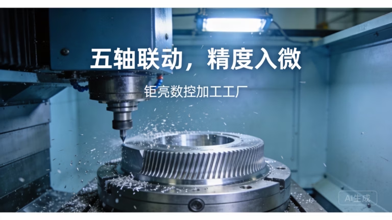
The three letters, decoded
CNC means computer numerical control. A part program made of numbered instructions replaces the handwheels a machinist once turned. Each line of that program is a coordinate, a feed rate, a spindle speed or a tool change. The controller reads the line, then commands servo motors to move the tool or the workpiece to that position.
The word numerical is the important one. Coordinates are numbers, and the machine holds them in a fixed reference frame. Once an operator touches off the workpiece, every feature of the part shares that same origin, so feature-to-feature position is repeatable across a whole batch.
What does cnc mean machining in practice? It means a digital file drives a cutting tool through metal, plastic or composite. The material is removed, not added or formed. That single fact sets the boundaries of the process, including the part shapes it handles well and the ones it cannot.
- 1CNC = computer numerical controlCoordinates and feeds written as code, executed by the machine controller.
- 2SubtractiveMaterial is cut away from solid stock, so deep internal cavities are limited by tool reach.
- 3RepeatableThe same program produces the same geometry on part one and part ten thousand.
From CAD model to cutting tool
Everything starts with a 3D model in CAD software. That model carries the nominal dimensions, the tolerances and the surface finish callouts. A good model also tells the machinist which faces are datums, because datums decide how the part will be held and probed.
A CAM programmer imports the model and builds the toolpath. Tool diameter, stepover, stepdown, feed rate and spindle speed all go into that decision. A 6 mm carbide end mill at 8,000 rpm and 1,200 mm/min in 6061 aluminium behaves nothing like the same cutter in 316 stainless, where the same slot may need 400 mm/min and a smaller radial engagement.
Post-processing turns the toolpath into machine-specific code. Then setup happens on the floor: vise or fixture, tool presetting, and a touch probe to establish the workpiece position in the machine coordinate system. Probe error of 0.01 mm becomes 0.01 mm of error on every feature referenced to that face.
The first article comes off the machine and goes to inspection. If the drawing calls ±0.005 mm, the shop checks the critical features on a CMM rather than trusting the machine's own readout. Only after that check does the run continue.
- 1CADNominal geometry, tolerances, datum callouts.
- 2CAMTool selection, stepover, feeds and speeds, toolpath order.
- 3Post and setupMachine-specific code, workholding, probing.
- 4First articleCMM or gauge check against the drawing before the run continues.
Axes, servos and what the controller actually controls
A three-axis mill moves the tool in X, Y and Z. A four-axis machine adds rotation, usually the workpiece turning on a rotary table. A five-axis machine adds a second rotary axis, so the tool can approach a face from an angle instead of only from above. GreatLight runs 16 simultaneous five-axis machining centers, 12 four-axis mills, 27 three-axis machines and 16 mill-turn centers.
Simultaneous five-axis means all axes move at the same time while cutting. That is different from 3+2 positioning, where the table tilts to an angle, locks, and then the cut happens in three axes. Positioning is cheaper and stiffer; simultaneous motion handles contoured surfaces and undercut features in one setup.
Each linear axis rides on a ballscrew or linear motor and reports position through an encoder. The controller compares commanded position with encoder feedback thousands of times per second and corrects the servo. Backlash, thermal growth and screw pitch error all show up as position error, which is why machine geometry is calibrated on a schedule.
The spindle is the other half of the system. Its runout, taper condition and thermal state set the floor for surface finish. A spindle with 0.005 mm runout cannot hold a tight bore no matter how good the program is.
- 13-axisX, Y, Z only. Flat faces, pockets, holes from one direction.
- 24-axisAdds rotary indexing or continuous rotation around one axis.
- 35-axisTwo rotary axes, simultaneous or 3+2 positioned.
- 4Mill-turnTurning and milling in one setup for round parts with milled features.
Where the ±0.005 mm budget goes
A tolerance on a drawing is a total budget, not a target. Machine positioning, thermal drift, tool wear, workholding deflection and measurement uncertainty all spend part of it. If each contributor eats 0.002 mm, the stack is already over a ±0.005 mm limit.
Thermal effects are easy to underestimate. Aluminium expands roughly 23 μm per metre per degree Celsius. A 500 mm part that warms 5 °C during a long roughing cycle grows about 0.06 mm before finishing even begins. Shops manage this by roughing, letting the part rest, then finishing.
Tool wear moves one direction. A carbide insert that has cut 200 parts is not cutting the same diameter as a fresh one. In-process gauging or scheduled tool changes keep that drift inside the budget.
Surface finish is a separate callout. As-machined surfaces sit around Ra 1.6–3.2 μm, a good finishing pass reaches Ra 0.8–1.6 μm, and a fine finish with a small stepover can reach Ra 0.2–0.8 μm. Surface roughness and dimensional tolerance are not the same requirement, and drawings should state them separately.
- 1Machine and setupPositioning error, fixture deflection, probe error.
- 2ThermalSpindle and workpiece growth during long cycles.
- 3Tool wearGradual diameter and edge-radius change across a run.
- 4InspectionGauge and CMM uncertainty counts against the same budget.
Material choice changes the whole plan
Aluminium is the default for prototypes and housings. Grades like 6061, 7075 and 6082 cut fast, hold good finish and take anodizing well. 7075 is stronger but less weldable and more prone to stress movement after roughing.
Stainless and steel raise cutting forces and heat. Grades such as 304, 316L and 17-4PH need lower surface speed, more rigid workholding and often a roughing pass followed by a stress-relief rest before finishing. Tool life drops, so the cost per part rises with the same geometry.
Titanium and nickel alloys like Ti-6Al-4V and Inconel cut slowly and generate heat at the edge. A part that takes 20 minutes in aluminium can take two hours in Inconel. That is a material property, not a scheduling problem.
Plastics bring their own rules. POM and PEEK machine cleanly but move with temperature; ABS and PC soften if the coolant and speed are wrong. Carbon fibre eats tool edges, so diamond-coated cutters are common.
- 1Aluminium6061, 2024, 5052, 6061-T6, 7075, 6082, ADC12.
- 2Stainless303, 304, 316L, 17-4PH, 440C, 420.
- 3Steel and titanium4130, 4140, 4340, tool steel, Ti-6Al-4V, Inconel.
- 4PlasticsABS, PC, POM, PA, PEEK, PP, HDPE, carbon fibre.
Where CNC stops making sense
CNC is subtractive, so the tool has to reach the material it removes. A cavity narrower than the smallest available cutter, or a channel that bends inside the part, cannot be machined from the outside. Additive processes build those features layer by layer.
Internal corners carry the tool radius. A 6 mm end mill leaves a 3 mm corner radius. If the drawing asks for a sharp internal corner, the design needs a relief notch or the corner has to be cut by EDM.
Unit cost scales with cycle time, not with part size alone. For simple shapes in high volume, die casting, stamping or injection moulding spread the tooling cost across thousands of parts and win on price. CNC wins when the part is complex, the volume is low, or the geometry changes between revisions.
Wall thickness matters too. Thin unsupported walls deflect under cutting force and chatter. Below roughly 0.5 mm in aluminium, the setup becomes the hard part rather than the toolpath.
- 1Tool reachNo cutter, no feature. Deep pockets and curved internal channels are out.
- 2Corner radiusSharp internal corners need EDM or a design change.
- 3VolumeHigh-volume simple parts belong to casting or stamping.
- 4Thin wallsBelow about 0.5 mm, deflection and chatter dominate.
When CNC fits, and when it does not
Judged on geometry, lot size and material, not on machine availability.
| Situation | CNC | Better alternative |
|---|---|---|
| Tight tolerance, ±0.005 mm | Yes | — |
| Prototype or bridge parts | Yes, no MOQ | — |
| Hard metal, titanium or Inconel | Yes | — |
| Undercut contours | Yes, 5-axis | — |
| Thin wall under 0.5 mm | Difficult | Sheet metal or additive |
| Deep narrow cavity | Limited by tool reach | Additive or EDM |
| 10,000+ simple parts | Costly per part | Die casting or stamping |
| Hollow internal channels | Not possible | 3D printing or casting |
| Sharp internal corners | Radius equals tool radius | EDM or broaching |
The short version
If the part is complex, low to mid volume, and needs tight tolerances or hard material, CNC is the right route. If it is a simple shape at 10,000+ pieces, or it has internal channels no cutter can reach, pick casting, stamping or additive instead and keep CNC for the tooling and the first articles.
Frequently asked questions
What does CNC stand for, and does the machine work on its own?
CNC stands for computer numerical control. The machine executes a stored program of coordinates, feeds and speeds.
It does not plan cuts or choose tools. A programmer makes those decisions, and an operator sets up the workpiece and verifies the first article before the run continues.
How tight a tolerance can CNC hold in production?
On a rigid setup with stable temperature, ±0.005 mm is achievable on critical features, and ±0.0002 in is the same figure.
The limit depends on the feature, the material and the measurement method. A long thin bore and a short flat face do not share the same realistic tolerance, even on the same machine.
Does CNC mean machining only covers milling?
No. The same control principle drives lathes, mill-turn centers, grinders and routers.
Milling covers prismatic parts and pockets; turning covers round parts. Mill-turn machines combine both so a shaft with milled flats comes off in one setup.
What file do I need to send for a quote?
A STEP or IGES model plus a 2D drawing with tolerances, datums and finish callouts. If you only have a drawing, we can work from that.
A DFM review within 12 hours flags features that are hard to hold, such as deep pockets, sharp internal corners or walls under 0.5 mm.
Is CNC suitable for one part?
Yes. There is no minimum order quantity, so a single prototype runs on the same machines as a 10,000-part order.
The setup cost is spread over one part, so unit price is higher. That still beats paying for tooling before the design is frozen.
How long does the first batch take?
Quotation and DFM analysis come back within 12 hours, and production can start within 24 hours of approval.
Machined parts typically ship in 3–5 days. Schedules depend on material availability and the finishing steps the part needs.
Send the drawing, get a DFM review
Upload a STEP file and we return a quotation with manufacturability notes within 12 hours. Uploads stay confidential, and an NDA is available on request.
12-hour quote±0.005 mmNo MOQ100% inspection
GreatLight elsewhere
We publish setup notes, tooling trials and inspection data from the factory floor.











