
Stack Mold High Cavitation Efficiency
A stack mold puts two or more parting lines on one machine axis, so one clamp force fills two sets of cavities per cycle. This page explains where that gain comes from, where it leaks away, and which plate tolerances decide the outcome. Written for tooling engineers and buyers sizing a high-cavitation tool.
In this article
- 1
- 2
- 3
- 4
- 5
- 6
- 7
- 8
- 9
How a stack mold multiplies cavitation
A stack mold carries two or more parting lines along the machine axis instead of the single parting line of a standard tool. When the press opens, every parting line separates at the same moment. Melt arrives from one hot runner manifold and feeds the cavity sets in parallel, so one cycle produces two, three, or four times the parts of a single-faced tool of similar footprint.
The clamp force is the reason this works at all. Tonnage is set by projected area, not by part count. Splitting the cavities across two parting lines keeps the projected area per plate lower, so a machine that already runs a 32-cavity single-face mold can often run a 2 × 32 stack without a larger press. That is the whole economic case.
Stack mold high cavitation efficiency is not the same as cavity count. A tool with 96 cavities that drifts out of balance, flashes on one plate, and drops parts on the second parting line produces less good output than a well-behaved 48-cavity stack. Efficiency is measured in good parts per hour per square meter of floor space, not in nominal cavity number.
The mechanism also sets the limits. Every extra parting line adds stack height, more leader pin engagement, more plates that must stay parallel under load, and more chances for the melt to short-fill one cavity set before the other. Those are machining and assembly problems before they are molding problems.
- 1Two parting linesDoubles output without raising clamp tonnage.
- 2Shared manifoldOne melt delivery system feeds both cavity sets.
- 3Stack height growsMore plates, more parallelism risk under load.
Where the gain leaks away: balance and breathing
Filling balance decides whether the second parting line helps or hurts. If runner dimensions, gate sizes, and cooling channels differ between the two halves, one set fills early and packs harder. The other set sees lower pressure, shorter hold, and heavier shrinkage. The tool then runs at the slower half's cycle, and the theoretical gain is gone.
Mold breathing is the second leak. During injection, clamp force deflects the plates slightly and the parting lines separate by a few microns. Venting depends on that movement being uniform. If one plate is stiffer or sits on a high spot, the gap opens unevenly: one zone vents well and the other traps gas. Burn marks and short shots appear in the same locations every cycle.
Thermal symmetry matters just as much. Two cavity sets stacked on one axis share the platens, but not necessarily the same heat history. A manifold that runs hotter on the stationary side will push more melt into the cavities nearest the sprue. Balanced manifold layout, symmetric cooling circuits, and matched insert fits keep the two halves filling alike.
You can measure all of this before the tool is cut. Flow simulation on the stacked layout shows fill imbalance in grams and percent. If the two cavity sets differ by more than a few percent in fill time, fix the runner or the gate before committing to steel.
Plate parallelism and flatness tolerances that carry clamp force
Clamp force travels through the full stack height. Every plate in that column has to pass the load on without creating a pressure point. A plate that is out of parallel by 0.01 mm across its span will concentrate force on the high corner and let the opposite corner breathe open. Localized flash starts there.
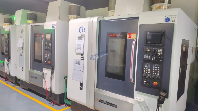
For stack tooling we hold flatness and parallelism to ±0.005 mm across the plate span, with plates up to 4,000 mm machined on high-rigidity 5-axis centers using in-process probing. The geometry is checked on a CMM before dowel holes and pockets are wire-EDM'd, because the plate faces become the datum for everything that follows.
Order of operations matters. Rough the plate, stress relieve, semi-finish, then finish both faces in the same setup where possible. If you flip the plate between face operations and rely on the vise, you inherit the vise's error. Once the faces are established, dowel holes and pocket locations are referenced from them, not from an edge.
Thin plates are the common failure. A plate that meets ±0.005 mm on the bench can deflect under 200 t of clamp force if the support spacing is too wide. Ribbing, support pillars, or a thicker section near the sprue often costs less than chasing flash on the press.
- 1Faces firstEstablish flat faces before any pocket or dowel hole.
- 2Same-setup finishingAvoid inheriting vise error on the second face.
- 3Support spacingThin plates deflect under load even when flat on the bench.
Cavity and core insert fits, slides, and lifter alignment
Insert fits set the repeatability of the whole stack. Cavity and core inserts are located by pockets cut into the plate, so pocket depth tolerance directly controls shut-off height. A pocket that runs 0.02 mm deep shifts the shut-off and changes the vent gap on that station. Hold pocket depth to ±0.005 mm and the stack closes the same way every cycle.
Slides and lifters add moving mass to the opening stroke. In a stack, they must travel in sync across both parting lines, or one half releases before the other and drags the part. Guide surfaces are usually ground and fitted with 0.01–0.02 mm clearance; anything looser shows up as wear in a few thousand cycles, anything tighter seizes when the tool reaches running temperature.
Ejection is where the two halves most often disagree. Ejector plates on stacked tools need matched stroke and matched return. If one set returns late, the next closing stroke crushes a pin. Spring return, positive return, and stroke sensors on the second parting line are common answers.
Hot runner alignment ties it together. The manifold sits between plates that move, so its locating diameters and dowel positions must match the plate bores within a few microns. A manifold that is off-center by 0.03 mm will leak at the nozzle seat once the tool is hot.
Material choices for high-cavitation stack molds
Plate steel is usually 1.2311, 1.2738, or P20 for the main plates, with 1.2343 or 1.2344 for inserts that see abrasive or heat-sensitive resins. Hardness in the low 30s HRC holds dimensions without making the plate difficult to machine. For long runs on glass-filled resin, pre-hardened plate at 38–42 HRC or a nitrided surface pays back in pocket wear.
Cavity and core inserts move to tool steel or stainless when the resin is corrosive. PVC, acetal, and some flame-retardant grades release acids that pit ordinary steel. 420 or 420 stainless holds up better and polishes well; 17-4PH is used where both corrosion resistance and higher strength are needed.
Copper alloys matter for cooling rather than structure. Beryllium copper inserts in hot spots pull heat out of thick sections faster and shorten cycle time. They machine easily but are soft, so they belong in areas that do not carry clamp load.
Hot runner manifolds are typically H13 or a comparable hot-work steel, with nozzle tips in a harder grade. The manifold is a pressure vessel at 250–300 °C; material choice follows temperature and resin chemistry, not cavity count.
When a stack mold is the wrong answer
Thick-wall parts rarely justify stacking. A part with a 6 mm wall needs long hold time, and hold time does not shrink when you add a second parting line. The press is occupied for the cooling phase either way, so the second cavity set buys less than the plate cost adds.
Large, heavy parts push the other way. A part that needs most of the platen area on a single face cannot be split across two faces without exceeding machine tie-bar spacing. Stack height also grows, and some presses run out of daylight before they run out of tonnage.
Short runs and frequent design changes are a poor match. A stack tool carries more plates, more fits, and more alignment features, so every engineering change costs more to implement. If the part is still moving, a single-face tool gets you to market sooner.
Family tools and low-volume medical or aerospace work usually stay single-face for traceability and validation reasons. Stack tooling earns its place in stable, high-volume programs where the annual part count is already known.
From print to running stack: the machining sequence
The work starts with DFM. We review the part print, wall sections, gate locations, and the planned stack layout, then return a quotation and DFM analysis within 12 hours. Simulation on the stacked cavity layout shows fill balance before any steel is cut.
Plate machining follows the datum logic. Faces are finished first, then dowel holes and pockets are wire-EDM'd from those faces, with in-process probing to confirm position. Inserts are machined to the pocket dimensions, not the nominal print, so the fit is set by measurement rather than assumption.
Assembly is where the stack proves itself. The tool is closed on the bench and checked for shut-off contact across all parting lines, then checked again hot. We inspect 100% before shipment with raw material, in-process, and final checks; reports are available on request.
Production can start within 24 hours of an approved drawing for standard work, and parts ship in 3–5 days for production runs. For tooling programs the schedule follows the plate and insert machining sequence rather than a fixed promise.
Five checks before you commit to a stacked layout
- 1Confirm annual volumeStack tooling pays back above roughly 500,000 parts per year for small parts. Below that, run the numbers on a single-face tool first.
- 2Check press daylight and tie barsAdd the full stack height and runner system to the mold height, then compare with machine daylight and tie-bar spacing before quoting.
- 3Run fill balance simulationCompare fill time and pressure between the two cavity sets. Aim for under 3% fill-time difference before cutting steel.
- 4Set plate flatness and parallelismSpecify ±0.005 mm across the plate span and require CMM reports for the plates that carry clamp load.
- 5Define ejection and return logicDecide matched stroke, positive return, and sensing on the second parting line before the ejector plates are cut.
Stack mold versus single-face tool: when each one fits
Use the left column when output per floor area is the constraint; use the right column when simplicity and lower tool cost win.
| Criterion | Stack mold | Single-face tool |
|---|---|---|
| Cavitation for same tonnage | 2× to 4× per cycle | 1× baseline |
| Clamp tonnage required | No increase for same part | Set by total projected area |
| Plate flatness / parallelism | ±0.005 mm needed | ±0.01 mm usually workable |
| Parting line count | Two or more | One |
| Ejection complexity | Matched stroke on both lines | Single ejector system |
| Hot runner cost | Shared manifold, higher cost | Simpler, lower cost |
| Best fit | High-volume, small-to-mid parts | Low volume, thick or heavy parts |
| Maintenance access | More plates, more teardown | Faster to service |
The short version
If your part is small, the volume is steady, and floor space is the bottleneck, a stack mold doubles output on the same press. If the part is thick, heavy, or still changing, a single-face tool will get you to market with less risk and less to maintain.
Stack mold questions engineers ask
Does a stack mold need a bigger injection unit?
Shot size roughly doubles because you are filling two cavity sets per cycle. The clamp tonnage often stays close to the single-face figure, but the barrel capacity and recovery rate have to be checked. If the injection unit cannot plasticize the doubled shot within the cooling time, cycle time grows and the gain shrinks.
How much plate flatness do stack molds really need?
For plates that carry clamp load through the stack, we hold flatness and parallelism to ±0.005 mm across the span. Looser plates concentrate force on a high corner and let the opposite side breathe open, which shows up as localized flash and uneven venting.
A single-face mold is more forgiving because the load path is shorter.
Can a stack mold run two different parts?
Yes. Family stack tools run one part on the first parting line and a second part, often a mating half, on the other. The constraint is that both parts must share a compatible cycle time and material. If one part needs much longer cooling, the tool runs at the slower part's cycle.
What causes short shots on only one parting line?
Uneven melt delivery is the usual cause. Check nozzle seat alignment, manifold temperature symmetry, and runner dimensions between the two halves. A manifold that runs hotter on one side pushes melt toward the nearest cavities and starves the far set.
Venting imbalance can produce the same symptom, so check both before changing process settings.
How does stack height affect maintenance?
More plates mean more teardown steps, more fits to inspect, and longer assembly time. Plan for leader pin and bushing inspection on every parting line, and keep spare ejector pins for both sets. Downtime per event is longer than on a single-face tool even when the failure rate is the same.
Is a stack mold suitable for medical or aerospace parts?
It can be, but validation cost is higher because more cavities and two parting lines are involved. Most programs in those industries start single-face for the first article and qualification, then move to a stack layout once the design and process are frozen.
Send us your stack mold plates and inserts
Upload drawings for a quotation and free DFM analysis within 12 hours. Plates up to 4,000 mm, flatness and parallelism held to ±0.005 mm, 100% inspection before shipment.
12-hour quote±0.005 mm plates100% inspection
More mold tooling engineering notes
We publish setup notes, tooling trials and inspection data from the factory floor.











