This paper introduces the machining center composed of turning and milling controlled by virtual Y axis as the test object by testing the verticality of virtual Y axis, positioning accuracy, interpolation accuracy and circular accuracy as well as other associated precisions, and optimizing compensation via the CNC. system, thus methods to improve the processing precision of machine tools.
PART 1Preface
At present, my country’s CNC machine tool production capacity and consumer market size lead the world. However, in the mid-to-high-end, high-precision multi-axis linkage compound processing machine tool market, Japanese and German companies. are in a leading position, which has become a challenge for the development of China’s manufacturing industry. With the continuous development of domestic aerospace, new energy, medical equipment and other industries, there is currently a demand for mid-to-high-end compound turning and milling machining centers, machine tools CNC in CNC lathe market, especially for turning centers with Y Axis The number of customers is increasing day by day.[1]。
The Y axis of the compound turning-milling machining center generally has two structural forms: the orthogonal Y axis and the inclined Y axis (that is, the virtual Y axis). Compared with the orthogonal Y-axis structure, the virtual Y-axis has the characteristics of high rigidity and compact overall structure. It can flexibly reduce the height of the machine tool and make the overall structure of the machine tool more compact. Over time, the movement of the Y axis can improve the milling ability of the cylindrical keyway of the machine tool. The turn-mill compound machining center with virtual Y axis can be widely used in workpiece processing fields such as precision and complex grooves, off-center drilling and tapping.
A certain model of machining center composed of turning and milling with virtual Y axis structure independently developed by our unit. The bed guide rail of the Y axis is tilted 40° from the horizontal direction, and the X axis is tilted 70°. horizontally. The structure has great rigidity. The control system adopts Japanese FANUC 0i TF PLUS system (or other high quality systems at home and abroad) and AC servo motor, easy to operate and reliable. It can carry out various turning, drilling and milling processes on various. parts within the processing range.
In order to better debug, test, test, apply and optimize the relevant functions of the Y axis virtual structure of the turn-mill composite machining center[2]so that the machine tool can finally achieve the best actual processing application effect, this time the following test was carried out.
PART 2 Virtual Y-axis linkage interpolation control technology
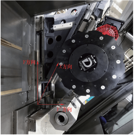
Debugging First, debug the virtual Y axis linkage interpolation control. The structure of the machine tool is shown in Figure 1. The lathe axis is composed of .
Figure 1: Virtual machine tool structure composed of Y-axis turning and milling
When directly using the tilted Y axis for programming, assuming that the turret must move a distance YL’ in the direction of the virtual Y axis perpendicular to the Y axis’), and the other axis positions remain unchanged, then the actual programming must be Move the X and Y axes for linked interpolation. The travel distances XL and YL are respectively:
XL=YL′/tan30°(1)
YL=YL′/sin30°(2)
It is more difficult to write programs directly, especially when the X and Y’ axes are linked. Therefore, it is necessary to debug the tilt axis function of the CNC system, so that the X axis and Y axis can do it. be programmed and controlled orthogonally, thereby reducing the difficulty of programming. During checking, it should be ensured that the imaginary axis of the Y axis is perpendicular to the X axis and the positive direction is upwards, as shown in Figure 2.

Figure 2 Y-axis tilt control
To use the Y axis as tilt axis control, you must select and activate the “Tilt axis control” function. In the FANUC 0i TF PLUS CNC system, you can determine whether the system has activated this function via the parameter diagnostic number. 1270#0.
Main parameters: In the FANUC 0i TF PLUS system, the main adjustment parameters[3]See Table 1.
Table 1 Y-axis positioning accuracy comparison

PART 3 Virtual Y-axis vertical compensation
The angle between the X axis and the real Y axis is 30° Thanks to the interpolation operation of the system, the angle between the virtual Y axis and the X axis is 90° when moving . However, due to the inevitable small errors during parts processing and assembly, the actual angle between the X axis and Y axis may not be exactly 30°. It is therefore necessary to determine the actual angle between the System 8210 parameters to be able to do this. ensure that the perpendicular between the virtual Y axis and the X axis during movement can meet the standard requirements. There are two methods to follow: the workpiece trial cutting method and the inspection tool measurement and debugging method.
3.1 Part test cutting method
Through actual test cutting of the workpiece on the machine tool, milling along the actual X-axis and Y-axis directions was carried out to determine the actual motion trajectories of the measurement. included angle and compensate the actual measured value against the tilt axis angle. Parameter 8210, as shown in Figure 3.

Figure 3 X-axis-Y-axis angle test compensation
3.2 Gauge measurement and debugging method
In order to simplify the testing and debugging process, a special inspection tool for the verticality of the virtual Y axis is designed this time. As shown in Figure 4, the inspection tool is used to replace the actual cutout for verticality adjustment.

Figure 4 X-axis-Y′ axis verticality measuring device
The two adjacent sides of the inspection tool are perpendicular to each other (<0.003/200). During inspection, switch the spindle to C-axis mode, adjust the C-axis angle, move the tool turret in the X direction, check the reading through the dial indicator, make the right angle side of the X direction of the inspection tool is parallel. to the movement of the X axis, then keep the position of the C axis unchanged, move the turret along the Y' direction of the virtual Y axis, read the difference a between the two ends of the dial indicator in the direction Y' of. the inspection tool calculates the theoretical angle deviation value θ' and superimposes this deviation value to compensate in parameter 8210.
θ′=arctan(a/L) (3)
In the formula, L is the measured length of the right angle side of the inspection tool (mm). After practical application testing, the vertical adjustment of the virtual Y-axis and X-axis can be quickly performed through this inspection tool.
PART 4 Virtual Y-axis positioning accuracy test compensation technology
Virtual Y-axis positioning accuracy testing and compensation technology. Because in real processing applications of machine tools with virtual Y axis structure, the actual movement of the Y axis is compound interpolation movement, so the positioning accuracy of the virtual Y axis needs to be tested and compensated. In the FANUC CNC system, parameters such as pitch error compensation and backlash compensation all correspond to the actual X axis and the actual Y axis. The actual test compensation object is the virtual Y axis. If there is any inconsistency between the two, two methods can be adopted to solve the problem: one is to test and compensate the actual Y axis, and rely on the accuracy of the X axis and l real Y axis. Real Y axis to indirectly ensure the linkage accuracy of the virtual Y axis; The second is to test the virtual Y axis and compensate it against the real Y axis based on the calculated data. The following is a comparison of the effects of the two compensation methods.
4.1 Test and compensate the real Y axis, indirectly guaranteeing the virtual Y axis
The positioning accuracy of real X-axis and real Y-axis was actually tested and pitch error compensation was performed, then the virtual Y-axis was tested. The test results are shown in Figure 5. The RENISHAW XL80 laser interferometer is used to test the positioning accuracy on the Y axis of the machine tool.

Figure 5 The positioning accuracy of the virtual Y axis after testing and compensation of the real Y axis
4.2 Test the virtual Y axis and compensate against the real Y axis according to the calculation
The positioning accuracy test results of the virtual Y axis after compensation are shown in Figure 6.

Figure 6 After testing the virtual Y axis, the positioning accuracy of the virtual Y axis is converted to the real Y axis after compensation.
4.3 Comparison of the effects of two compensation modes
The comparison of the effects of the two compensation methods is presented in Table 2.
Table 2 Comparison of Y-axis positioning accuracy

It can be concluded from the test results that by testing the virtual Y axis and compensating the real Y axis after proportional calculation, the step error is lower than that of direct Y axis testing and compensation real, and the accuracy is significantly improved.
PART 5 Servo optimization test uses FANUC SERVO GUIDE software to perform servo optimization test settings on the power axis, including the virtual Y axis, mainly including: adjustment of the servo constant fast movement time of each axis, standard arc test (XZ plane), tilted axis. arc test (XY plane), square test, square test with 1/4 arc, Cs contour control test, vibration frequency test and servo frequency response test, etc., as shown on Figures 7 to 9.

a) Setting the rapid movement time constant b) Arc test
Figure 7 Setting the Rapid Travel Time Constant and Arc Test

a) Square test b) Square test with 1/4 arc
Figure 8 Square test, square test with 1/4 arc

a) Cs contour control test b) Servo frequency response test
Figure 9 Cs contour control test, servo frequency response test
The adjustments mainly focus on several aspects such as speed and position gain, post-interpolation time constant, arc radius deceleration, allowable speed difference for corner deceleration, time constant d cutting feed and speed anticipation.
By backlash, reversal peaks, cyclic error, scaling mismatch and servo mismatch[4]In other aspects, the main parameters of the FANUC system are optimized and adjusted to improve the dynamic performance of the machine tool. Parameters include: No.1622 (acceleration and deceleration time constant after interpolation for the cutting feed of each axis), No.1769 (acceleration and deceleration time constant after interpolation), No.2005 #1 (valid anticipation), No.2092 (anticipation coefficient advance) and #1825 (position loop gain), etc.[5]。
PART 6 Actual Processing Application Test
In order to verify the effect of debugging the Y axis accuracy, the NAS sample was tested before and after adjustment (see Figure 10), and the machining accuracy and surface quality were compared .

Figure 10 Processing NAS samples
6.1 Processing accuracy comparison test
The comparison of machining accuracy is shown in Table 3.
Table 3 Comparison of NAS sample accuracy

It can be concluded from the test results that the processing accuracy has been significantly improved after optimization and adjustment.
6.2 Comparative test of the quality of machined surfaces
The surface quality comparison of Y-axis virtual milling before and after servo optimization is shown in Table 4.
Table 4 Comparison of machining surface quality on virtual Y axis

Before servo optimization, there were obvious cutting vibration patterns on the machined surface. After optimization and adjustment, the surface vibration models were significantly improved. Before optimization and adjustment, the surface roughness value Ra = 1.3 μm, and after optimization and adjustment, the surface roughness value Ra dropped to 0.7 μm. It can be concluded from the above experimental test results that after adjusting the servo optimization tests, the precision and surface quality of the cutting parts have been significantly improved.
PART 7Conclusion
This article introduces the structure of a turning center with a virtual Y axis, as well as the verticality test and compensation of the XY plane, the positioning precision test and compensation of the virtual Y axis, the adjustments of optimization of related servos, comparison of actual cutting NAS parts, etc. and draws the following main conclusions.
1) Testing the actual angle between the X-axis and the real Y-axis via two methods, or compensating via the system parameters, can ensure that the verticality between the to the usage requirements.
2) Comparing the actual application of two pitch error compensation methods for the positioning accuracy of the virtual Y axis, it is proved that by directly testing the positioning accuracy of the virtual Y axis, and then by compensating the real Y axis pitch error compensation data after proportional calculation, it is better than testing the real Y axis. Axis positioning accuracy and pitch error compensation are carried out to indirectly ensure the positioning accuracy of the virtual Y axis, and the effect is greatly improved.
3) Through the SERVO GUIDE software of FANUC system, the relevant servo parameters of the machine tool system are optimized and adjusted, which can significantly improve the machine tool movement interpolation accuracy, roundness accuracy milling interpolation of the machine tool processing specimen, the Y axis interpolation straightness and accuracy of parts, such as contour errors at corners, can also be considerably improved.
4) After comparing the accuracy of NAS specimens before and after machine tool optimization, the processing accuracy and machined surface quality were significantly improved. It can be concluded that the virtual Y axis, after relevant optimization and compensation adjustment, can achieve satisfactory practical application effects.
Daguang focuses on providing solutions such as precision CNC machining services (3-axis, 4-axis, 5-axis machining), CNC milling, 3D printing and rapid prototyping services.