1
Preface
The bogie is one of the key systems of railway vehicles. It not only provides traction and braking force during vehicle operation, but also ensures the quality of the entire vehicle. Its reliability is particularly important. As the main structure, the frame generally adopts an H-shaped all-welded structure, which connects the primary suspension, secondary suspension, vibration damping device, traction device, braking device, electric motor and the gearbox. The frame is made of medium thickness plates welded into a box-shaped structure to ensure the strength of the connection.
Below the frame are the main suspension-related components, such as axle boxes, vertical shock absorbers, etc. ; Above the frame are the secondary suspension-related components, such as air springs, side shock absorbers, etc. In order to ensure precise installation of each component, the front and rear sides of the frame must be processed, and the surface roughness Ra of the suspension mounting surface is limited to 6.3 μm. As the speed and carrying capacity of intercity EMUs increase, the vehicle operating environment becomes more and more complex. More and more components are installed on the chassis, and the processing requirements of the chassis are also higher and higher.
2
Process analysis
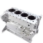
Figure 1 shows the structure of a 200-kilometer intercity EMU, with a typical H-shaped structure. The main processing positions on the rear side of the frame include the swing arm positioning seat, the suspension seat of the gearbox and bracket mounting surface; The main processing positions on the front side include the pull rod seat, the engine suspension seat and the brake suspension seat, etc. .
Figure 1 The structure of a 200 kilometer intercity EMU
Before processing the frame, all processing parts have been marked and checked, and unqualified positions have been adjusted to ensure that the required parts of the frame can be processed. Here we choose the processing method for the back side first, then the front side.[1]because there is a large flat area at the position of the cap tube in the inverted mounted state, and the position is also at the edge of the largest size of the frame, which is very suitable to be used as a rough reference for the treatment . By marking and alignment, the mounting surface on the back side is processed first, and then the finished machined surface on the back side is used as a reference to position the front side, thereby achieving precise processing of the front side.
3
Tool selection and parameter determination
3.1 Bracket mounting surface treatment plan
Use a high-speed steel end mill. Rotation speed n0 = 600 rpm, rear cut quantity ap = 1 mm, outer diameter of the cutter d0 = 80 mm, number of teeth z = 6, feed per tooth af = 0.13 mm/z, depth of the milling contact arc ae = 45 mm.
3.2 Treatment plan of rotating arm positioning seat
1) Vertical roughing of the interior facade of the swivel arm positioning seat. D63 end mill is selected to use layered cutting processing method and the tool material is high speed steel. Rotation speed n0 = 900 rpm, rear cut quantity ap = 3 mm, outer diameter of the cutter d0 = 63 mm, number of teeth z = 6, feed per tooth af = 0.22 mm/z, depth of the milling contact arc ae = 3 mm.
2) Vertical finishing of the interior facade of the rotating arm positioning seat. D25 end mill is selected to use layered cutting processing method and the tool material is carbide. Rotation speed n0 = 800 rpm, rear cut quantity ap = 5 mm, outer diameter of the cutter d0 = 25 mm, number of teeth z = 4, feed per tooth af = 0.06 mm/z, depth of the milling contact arc ae = 5 mm.
3) Rough machining of φ70mm hole for swing arm positioning seat. There is interference in vertical machining at this position, so a right angle head and corn milling cutter are used to process the tool using spiral feed. The tool material is high speed steel. Rotation speed n0 = 900 rpm, rear cut quantity ap = 0.5 mm, outer diameter of the cutter d0 = 50 mm, number of teeth z = 3, feed per tooth af = 0.44 mm/z, depth of milling contact arc ae = 0.5 mm.
4) Rough bore of φ70mm hole for rotary arm positioning seat. There is interference in vertical machining at this position, so a right angle head and a rough boring tool are used, and the tool material is high speed steel. Rotation speed n0 = 800 rpm, amount of backcut ap = 100 mm (effective bore), outer diameter of the cutter d0 = 69.6 mm, number of teeth z = 2, feed per tooth af = 0, 13mm/z, depth of milling contact arc ae =60mm.
5) Precision boring arm positioning seat with φ70mm hole. There is interference in vertical machining at this position, so a right angle head and a fine boring tool are used, and the tool material is high speed steel. Rotation speed n0 = 800 rpm, amount of backcut ap = 100 mm (effective bore), outer diameter of the cutter d0 = 70.1 mm, number of teeth z = 2, feed per tooth af = 0, 10mm/z, depth of milling contact arc ae =60mm.
3.3 Gearbox suspension treatment plan
There is interference in vertical machining at this position, so a right angle head and an end mill are used to process by layer cutting, and the tool material is high speed steel. Rotation speed n0=900r/min, rear cut quantity ap=2mm, outer diameter of the cutter d0=63mm, number of teeth z=6, feed per tooth af=0.22mm/z, arc depth of milling contact ae=2mm.
4 tooling design
For general machining procedures, the commonly used positioning method is an adjustable support on the lower part and a vertical downward pressing force on the upper part. In order to correct the dimensions of the X and Y coordinates of the part, an adjustment screw is added. the side. However, because this compression method is entirely achieved by friction, it is necessary to check the friction force and cutting force during processing to verify whether the compression is reliable.
The general weft processing tools are shown in Figure 2. The cap tube under the frame is supported by an adjustment cushion with a working area of 220mm × 120mm, and an opening pressure plate made of U shape is used for compression above. Auxiliary support and compression are added in places where frame rigidity is lower.

Figure 2 General frame processing tools
The following takes the largest mounting surface of the holder in reverse machining, which is also the position where the workpiece receives the greatest cutting force, as an example for verification. If this position can meet the compression requirements, then all other positions can meet the requirements. requirements.
4.1 Forces on the tool
Cutting force is a resultant force[2]its sources include: resistance to elastic deformation, resistance to plastic deformation and friction, etc. In order to facilitate measurement and application, the resultant force F can be decomposed into three mutually perpendicular components: the main cutting force Fz, the cutting resistance force Fy and the feed resistance force Fx, as the shown in Figure 3.

Figure 3 Breakdown of cutting force
4.2 Forces exerted on the part
The total cutting forces F′ and F acting on the workpiece are equal in magnitude and opposite in direction. Due to the design requirements of machine tools and accessories, the total cutting force is generally decomposed into the following three components: feed force Ff – the component of the total cutting force in the longitudinal feed direction, force of transverse feed Fe – the total cutting force in the transverse direction Component force in the feed direction, vertical feed force Ffn – the component force of the total cutting force in the vertical feed direction.
According to experiment, Ff=(0.3~0.4)Fz, Ffn=(0.85~0.95)Fz, Fe=(0.5~0.55)Fz.
4.3 Analysis of the constraints of the part
The force exerted on the part is:![]() . vertical direction:
. vertical direction:![]() horizontal direction:
horizontal direction:![]() . The friction force generated by the vertical feed force Ffn, the tool pressure force Fpressure and the gravity force of the workpiece must be greater than the resulting force of the feed force Ff and the force d transverse feed Fe. For the part to remain stable, the resulting horizontal force must be positive. The formula for calculating cutting force is
. The friction force generated by the vertical feed force Ffn, the tool pressure force Fpressure and the gravity force of the workpiece must be greater than the resulting force of the feed force Ff and the force d transverse feed Fe. For the part to remain stable, the resulting horizontal force must be positive. The formula for calculating cutting force is

In the formula KFz=(σb/0.637)0.3, treatment of carbon structural steel σb=0.637GPa.
The coefficients and indices of the cutting force formula are presented in Table 1. It can be seen that CF=78.5,

From Ffn=(0.85~0.95)Fz, we can approximately obtain Ffn=0.9×478.5=430.7(N); from Ff=(0.3~0.4)Fz, we can approximately obtain F f=0.35×478.5=167.5(N); from Fe=(0.5~0.55)Fz, we can approximately obtain that Fe=0.525×478.5=251.2(N). Then the resulting force on the horizontal plane of the tool on the workpiece is F2 = (Ff2 + Fe2) 1/2 = (167.52 + 251.22) 1/2 = 301.9 (N). Gravity G = mg = (1900/4) × 10 = 4750 (N).
Since the cutting process is extremely complex and the model building and formula usage are simplified to a certain extent during the calculation process, a larger safety factor of 10 is adopted and the thrust force external force exerted by the tool on the workpiece is approximately 3019N.
Table 1 Coefficients and exponents of the cutting force formula

4.4 Calculation of the pressing force of the pressure plate
Select M16 class 8.8 bolts. According to the corresponding manual, the tightening torque Mt of the bolt is 189N·m. The calculation formula is Mt=0.001KP0d. The formula for calculating the bolt pre-tightening force is as follows:
![]()
In the formula, P0 is the pre-tightening force (N); Mt is the tightening torque (N·m); K is the clamping force coefficient d is the nominal diameter of the thread (mm).
Consult relevant manuals[3]It turns out that K = 0.3. Substituting Mt = 189N·m and d = 16mm into equation (2), we obtain P0 = 189/(0.001×0.3×16) = 39375 (N).
Take the bolt and tighten it in the middle position, then the pressure exerted by the pressure plate on the workpiece is F pressure = P0/2 = 19687.5 (N).
4.5 Calculation of the maximum static friction force
Due to the presence of cutting fluid, the coefficient of static friction is taken as 0.05. Then the maximum static friction force Fdown on the bottom surface of the part = μN down = 0.05 × (Ffn + G gravity + F pressure) = 0.05 × (430.7 + 4750 + 19687.5) = 1243 ,4 (N); the maximum static friction force F on the upper surface of the part = μ N = 0.05 × F pressure = 0.05 × 19687.5 = 984.4 (N).
4.6 Conclusion of the strengths analysis
The friction force experienced by the workpiece in the horizontal direction is 2227.8 N and the thrust force given by the tool to the workpiece is 3019 N. Since the thrust force on the workpiece is greater due to friction on the upper and lower surfaces of the object, the workpiece is not reliably pressed and will move during the machining process. Therefore, in the design of frame processing tooling, the method of increasing side clamping is adopted to provide excessive horizontal force, so that the frame can remain stationary during the processing process.
5Conclusion
During the actual production process of the part, the stress situation is very complicated, and quality problems may occur if you are not careful. This article analyzes the processing technology of EMU intercity structure and calculates the force during the workpiece compression tooling process to determine whether the compression force in actual processing is reliable and whether the process plan is appropriate. similar parts.
Daguang focuses on providing solutions such as precision CNC machining services (3-axis, 4-axis, 5-axis machining), CNC milling, 3D printing and rapid prototyping services.