The processing efficiency of traditional lathes is low and the tools need to be improved. Homemade external oil groove cutter and inner hole oil groove cutter are used for processing inner hole and outer oil groove respectively. time, CNC lathe is used instead of horizontal lathe to process the spiral groove. The processing technology is optimized, and finally, the efficient and stable processing of the cross spiral oil groove is achieved through programming.
Preface
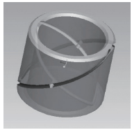
In plain bearings, crossed spiral groove structures are common in bushings or bushing parts, which are mainly used to store lubricating oil and promote oil lubrication.[1]. Figure 1 shows the structure of the spiral groove structure ring part to be processed. There are two oil grooves adjacent to the head and tail with opposite rotation directions at the outer circle and inner hole of the workpiece. intersect in X lines. There are small holes connected on the wall of the hole. The two small holes are spaced 180° apart in the circumferential direction. Small holes play a role in positioning the oil grooves during processing. through this hole. Other processing requirements for parts are: outer circle tolerance ±0.025 mm, inner hole tolerance ±0.021 mm, inner and outer circle tolerance
Coaxiality φ0.02 mm.
Figure 1 Structure of the helical groove bushing parts to be processed
The specific spiral structure of ring-shaped parts determines the difficulty of this structure in the actual processing process, and the currently described processing methods are difficult to use effectively.[2]. Analyzing the reasons, first of all, if a horizontal lathe is used to process a spiral oil groove, the pitch of the spiral is large. If the workpiece length is short, a very fast feed rate is required and manual retraction is necessary. required.
The formula is difficult to grasp precisely. Secondly, the spiral oil groove is divided into a left oil groove and a right oil groove. The steps of the indexing operation are tedious. If it is processed on a horizontal lathe, it must be tightened several times according to different rotations. directions, and the tool for processing the oil groove is also difficult to grind. Welded turning tools or white steel turning tools are usually ground by hand on a grinder, and then the tool head is adjusted according to the spiral angle and rotation direction of. oil groove, required front angle, rear angle and tool tip arc for detailed grinding.[3,4]slight negligence in the manual grinding process will lead to processing defects and repair will also be more difficult. This technology is difficult for general operators to master. At the same time, this method will cause low processing efficiency of spiral oil grooves, especially when processing larger batches of parts, it is often impossible to meet the order delivery time requirements.
traditional treatment methods
Previously, the processing of this type of product was carried out on a horizontal lathe. Since there is no encoder to provide spindle speed and angle information, the only option is to process the oil tank step by step, which requires 7 processes to complete a product . . The specific processing steps are as follows:
① Clamp the bar, drill the center hole, roughly turn and semi-finish the outer circle and inner hole of the product, chamfer and cut, turn around the end face and chamfer.
② Make 2 small holes on the drill wall, use the small holes to position the chuck, and turn the left outer circular oil groove.
③The right outer circular oil groove of the chuck lathe.
④After deburring the oil groove, tighten the outer circle and process the left inner hole oil groove.
⑤ Tighten the outer circle and process the oil groove of the right inner hole.
⑥ Tighten the outer circle for fine turning and boring.
⑦ Finely turn the outer circle of the through chuck.
Improve treatment methods
In order to improve the processing efficiency of batch products and ensure the stability of product quality, CNC lathes are used instead of horizontal lathes to process spiral grooves, and the processing tools and processes are improved and optimized to achieve efficient and stable processing of spiral grooves. thanks to programming.
3.1 Improvement of machining tools
Based on the tool structure used to process oil grooves on the original horizontal machine tool, we designed the outer spiral oil groove milling cutter and the outer spiral oil groove milling cutter. spiral with inner hole shown in Figures 2 and 3 respectively. They mainly consist of a cutter body, a. forming a cutting head, a compression screw and an angle. The dial is composed of several identical parts, and the spiral oil groove cutter in the inner hole is also equipped with an internal cooling hole. The main design idea is: when installing the tool, place the cutter head into the cutter body. At the same time, the cutter head can adjust the angle by manual rotation according to the size and direction of the propeller rise angle, adapting to the. the propeller rise angle and the rotation direction of the oil groove, and tighten it with screws. Finally, the oil groove indexing processing is converted into the tool angle adjustment processing, which greatly reduces the processing difficulty. This type of tool can also effectively reduce clamping steps during processing. For machining spiral grooves of inner holes, the upgraded tool installs the head of the forming tool in the front of the tool body, which is more convenient for tool cooling and l chip removal.

Figure 2 External Spiral Oil Groove Cutter
1—Formed cutting head 2—Cutting body 3—Compression screw 4—Angle dial

Figure 3 Spiral Oil Groove Cutter for Internal Hole
1—Compression screw 2—Cutter body 3—Internal cooling hole 4—Formed cutting head
Sharpening the cutting heads of the above two tools is also very simple and easy. If the width of the groove is 2mm, use φ2mm white steel drill bit, which can save the work of grinding in the width direction of the cutter head and simply use it. a regular grooving knife to sharpen it. You only need to make the corresponding front and rear angles and arcs, which reduces the difficulty of grinding the tool.
3.2 Improvement of processing technology
The SKT21 CNC machine tool was used for processing. After analyzing the machine tool performance and machining accuracy, a two-part processing plan was initially decided. Only 4 processes were required to complete the processing of both parts of the oil tank, which significantly improved the result. quality of oil tank parts. Processing efficiency, the combined processing of two copper rings is shown in Figure 4. The specific processing steps are as follows.

Figure 4 Combined processing of two copper rings
1) Tighten the bar, drill the center hole, roughly turn and semi-finish the outer circle and inner hole, cut an undercut groove on each of the inner and outer circles between the two products, cut and turn over. to chamfer the end face.
2) Drill 2 small positioning holes, use the small holes to position each other as clamping ends, and process the inner and outer circular oil grooves separately.
3) Continue to squeeze the ends together and finish turning the inner and outer circles.
4) Cut, flip and chamfer the end faces respectively.
3.3 Improvement of processing procedures
After using small hole positioning to process the first oil groove, I found that if the second, third and fourth oil grooves were processed without adjustment, the processed oil grooves would not be able to meet design requirements very precisely. If you want to process oil grooves separated by a certain distance and accurately pass through the positioning holes, you need to achieve precise indexing between different oil grooves. By analyzing the working principle of machine tool encoders[4]when the rotation speed remains unchanged, the tool tip cuts the workpiece each time from a fixed point. As long as the cutting point of the tool tip on the machine tool can be changed, precise indexing between the oil grooves can be achieved. After numerous machining tests and theoretical analysis, it was found that as long as the Z axis tool starting point is changed, the entry point position can be changed very effectively to achieve precise indexing of the processed oil groove. The part and its oil groove distribution are shown in Figure 5.

Figure 5 Finished parts and their distribution of oil grooves
When the workpiece is fixed in the central undercut, oil grooves with different rotation directions can be indexed by reversing the spindle, and the tool is advanced from right to left. The optimized design processing procedure is as follows.


Conclusion
This article explains the improved processing method of spiral oil groove products through the analysis of processing examples of cross spiral oil groove parts on the SKT21 CNC machine tool. This processing method only requires one tightening to obtain
The four oil grooves with different rotation directions are now processed, which reduces production time and improves production efficiency. The improved machining tools not only significantly
This reduces the difficulty of grinding tools and makes the tool easier to use. After the tool is worn out, only the tool head can be replaced to complete processing, which reduces production costs, improves economic benefits and improves processing precision. This processing method also has a certain reference significance for the processing of similar structural parts.
Daguang focuses on providing solutions such as precision CNC machining services (3-axis, 4-axis, 5-axis machining), CNC milling, 3D printing and rapid prototyping services.


