
Understand and configure the key parameters of the 960 vertical machining center
The 960 vertical machining center is a C-frame mill with a moving table, and most of its cut quality comes down to five settings. This page explains what each parameter physically does, the ranges that work on aluminum, steel and titanium, and when the machine is the wrong choice.
In this article
- 1
- 2
- 3
- 4
- 5
- 6
What the 960 vertical machining center actually is
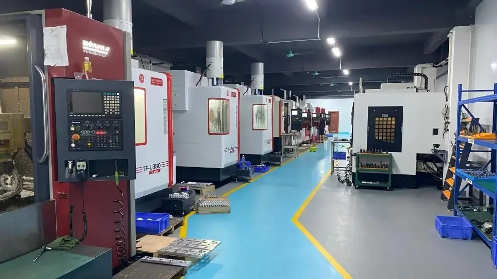
A 960 vertical machining center is a vertical-spindle mill with a fixed column and a table that travels in X and Y. The number refers to the nominal table or X travel, usually around 900 to 1,000 mm. The spindle stays vertical, the tool spins, and the workpiece moves underneath it. That layout gives good access to the top face of a part. It gives poor access to the sides and the bottom.
The structure matters because it sets the stiffness budget for every parameter you pick later. A C-frame column deflects under side load. When you push a large-diameter face mill, the column bends slightly away from the cut. That bending shows up as chatter, taper or a dull surface finish. Knowing this tells you why a 960 vertical machining center is happiest with moderate depths of cut and moderate feeds, not with brute-force hogging.
Compared with a horizontal machining center, a vertical machine has a shorter Z axis and simpler fixturing. Compared with a small 30-taper drill-tap mill, it is far more rigid and can hold ±0.005 mm on a well-set-up part. It sits in the middle. It is the workhorse for plate work, housings, brackets and fixtures, and it is the machine most shops reach for first.
Spindle speed and the cutting speed it produces
Spindle speed is the parameter people change most and understand least. What the cutter feels is surface speed, not rpm. Surface speed equals spindle speed times tool diameter times pi, divided by 1,000 to get meters per minute. A 10 mm end mill at 8,000 rpm runs at 251 m/min. The same rpm on a 50 mm face mill runs at 1,257 m/min, which will burn the inserts. Always convert rpm to surface speed before you decide.
The working ranges depend on material. Aluminum 6061 likes 300 to 600 m/min, so a 10 mm cutter wants roughly 9,500 to 19,000 rpm. Mild steel 1018 sits near 100 to 150 m/min. Stainless 316 sits near 60 to 100 m/min and work-hardens if you dwell. Titanium Ti-6Al-4V sits near 40 to 60 m/min and needs constant feed to keep the heat in the chip. If your spindle tops out at 8,000 rpm, a 10 mm cutter in aluminum will be speed-limited, and you should compensate with feed per tooth.
Spindle speed also sets the thermal load. Running at the top of the spindle range for hours raises bearing temperature, and the spindle grows in Z. On a long finishing pass, that growth can shift the depth by several micrometers. If your tolerance is ±0.005 mm, warm the spindle for 15 to 20 minutes at cutting speed before the first finish cut. Do not warm it at idle.
Feed rate, chip load and why feed is not a speed setting
Feed rate is the table speed in mm per minute. Programmers sometimes treat it as a way to slow the machine down. That is wrong. Feed rate controls chip thickness, and chip thickness controls heat. If you lower the feed but keep the spindle speed, the cutter rubs instead of cutting. The edge dulls, the surface tears, and the tool life drops. Feed and speed must move together.
The number to calculate first is chip load, or feed per tooth. Chip load equals feed rate divided by spindle speed divided by the number of teeth. For a 10 mm three-flute carbide end mill in 6061 aluminum, a chip load of 0.05 to 0.10 mm per tooth is reasonable. In 1018 steel, drop to 0.03 to 0.06 mm per tooth. In 316 stainless, drop to 0.02 to 0.04 mm per tooth. In Ti-6Al-4V, 0.02 to 0.05 mm per tooth with high-pressure coolant.
Three practical rules keep you out of trouble. Never let chip load fall below the edge radius of the insert, or the tool will rub. Keep the feed constant through the arc of a corner, or the chip thins and the edge rubs at the exit. And if the machine has look-ahead, use it. A 960 vertical machining center with good look-ahead can hold feed through tight corners, which is where most finish problems start.
Depth of cut, stepover and the stiffness limit
Depth of cut is how deep the tool bites in Z. Stepover is how far it moves sideways in X and Y. These two numbers decide the cutting force, and the cutting force decides whether the 960 vertical machining center stays quiet or starts to ring. A light, fast pass with a small stepover and a large depth of cut is usually better than a heavy, slow pass. The reason is radial engagement. A small radial engagement spreads the load along more of the flute, which pulls heat out of the cut and reduces deflection.
For roughing aluminum with a 12 mm end mill, a depth of cut of 1.5 to 3.0 times the tool diameter is realistic if the stepover stays at 5 to 10 percent of the diameter. For steel, keep the depth at 0.5 to 1.0 times the diameter and the stepover at 20 to 40 percent. For stainless and titanium, use a lower depth, around 0.3 to 0.6 times the diameter, and accept a slower removal rate. The machine will tell you when you exceed the limit. Chatter marks, a rising spindle load and a high-pitched noise are the signs.
The stiffness limit is not just the column. It is the whole chain: spindle, tool holder, cutter, vise and part. A long tool with a small shank will deflect before the column does. If you need a deep pocket, use the shortest tool that reaches, and reduce the depth of cut rather than the feed. Reducing feed makes the tool rub. Reducing depth keeps the chip load correct.
Tool offsets, work offsets and thermal drift
Tool length offset tells the control where the tip of each tool sits relative to the spindle gauge line. Work offset tells it where the part sits on the table. Get either wrong and the first rapid move will crash. Measure tool length on a presetter or with a touch probe, and recheck after any tool change. A 0.02 mm error in tool length shows up as a 0.02 mm error in Z on every feature that tool cuts.
Thermal drift is the quiet parameter. As the machine runs, the spindle, ballscrews and bed warm up and expand. On a 960 vertical machining center, the Y axis ballscrew can grow enough to shift the part by 10 to 20 micrometers over a long run. Two habits control it. Warm up the machine with a 15 to 20 minute cycle before the first tight cut. And if the run is longer than two hours, re-probe the work offset at intervals and let the control compensate.
Cutter compensation is the third offset to watch. It lets the operator adjust the finished size without reprogramming. Keep the compensation value small, and record it. If a machinist adds 0.05 mm of cutter comp to hit a bore size, the next operator will chase that number if it is not written down. On parts held to ±0.005 mm, the compensation value and the measured result should both go in the setup sheet.
Starting parameters by material on a 960 vertical machining center
Values for a 10 mm three-flute carbide end mill with through-coolant. Adjust for tool length, holder runout and part stiffness.
| Material | Surface speed | Chip load per tooth | Depth of cut |
|---|---|---|---|
| Aluminum 6061 | 300–600 m/min | 0.05–0.10 mm | 1.5–3.0 × Ø |
| Steel 1018 | 100–150 m/min | 0.03–0.06 mm | 0.5–1.0 × Ø |
| Stainless 316 | 60–100 m/min | 0.02–0.04 mm | 0.3–0.6 × Ø |
| Titanium Ti-6Al-4V | 40–60 m/min | 0.02–0.05 mm | 0.3–0.5 × Ø |
| Brass C36000 | 200–400 m/min | 0.05–0.10 mm | 1.0–2.0 × Ø |
| POM / PEEK | 200–500 m/min | 0.05–0.12 mm | 1.0–2.0 × Ø |
When to use the 960 and when to move on
Choose a 960 vertical machining center for plate work, housings and fixtures where you need ±0.005 mm on the top face and the sides are simple. Move to a 4-axis or 5-axis machine when the part has features on four or five faces, when you need a single setup, or when the part is long and slender. The 960 will not beat a horizontal machine on deep side milling.
Frequently asked questions
What tolerance can a 960 vertical machining center hold?
On a rigid setup with a warm spindle and a sharp cutter, ±0.005 mm is achievable on critical features. That is the tolerance we quote and inspect to.
Tighter than that on a long part is a different problem. Thermal drift and part deflection start to dominate, and you need in-process probing or a temperature-controlled room.
Is a 960 vertical machining center good for stainless steel?
Yes, with the right parameters. Stainless 316 work-hardens, so you must keep the chip load above the edge radius and never dwell in the cut.
Use surface speeds of 60 to 100 m/min, chip loads of 0.02 to 0.04 mm per tooth, and plenty of coolant. A slow, rubbing pass will dull the tool fast.
How do I reduce chatter on a vertical machining center?
First check the tool. A long tool with a small shank deflects before the machine does. Use the shortest tool that reaches and a shrink-fit or hydraulic holder.
Then reduce radial engagement, not feed. A smaller stepover lowers cutting force while keeping chip load correct. If chatter remains, raise the spindle speed slightly to move off the resonant point.
What is the maximum part size for a 960 vertical machining center?
The work envelope depends on the exact model, but the X travel is typically 900 to 1,000 mm. GreatLight runs machines with travels from 500 × 500 × 450 mm up to 4,000 × 400 × 150 mm.
If your part is longer than the table travel, the setup needs repositioning or a different machine. Send the drawing and we will confirm the envelope before quoting.
How long should I warm up the spindle before a finishing cut?
Run 15 to 20 minutes at the cutting speed you plan to use, not at idle. Idle warm-up heats the bearings unevenly and does not stabilize the spindle growth.
For runs longer than two hours, re-probe the work offset at intervals. That catches thermal drift before it eats your tolerance.
Can you machine my part on a 960 vertical machining center from a CAD file?
Yes. Upload the STEP or IGES file and we return a quotation plus a DFM analysis within 12 hours. There is no minimum order quantity, from one prototype to 10,000+ parts.
We machine aluminum, stainless, steel, titanium, copper alloys and engineering plastics, and we can apply anodizing, plating, powder coating or laser marking after machining.
Send us your part and the parameters stop being a guess
Upload a STEP file and our engineers will return a quotation, a DFM analysis and a suggested cutting strategy within 12 hours. No minimum order. Uploads are secure and confidential.
12-hour quote100% inspectionNo minimum orderNDA on request
More machining notes
We publish setup notes, tooling trials and inspection data from the factory floor.











