Navigating the World of CNC Machining: A Practical Guide from Design to Finished Part
For engineers, designers, and procurement professionals across industries, understanding how to transform a digital concept into a precision physical component is fundamental. The question “How to CNC machine?” encompasses far more than just pressing a start button on a machine. It represents a sophisticated, multi-stage engineering and manufacturing workflow that demands expertise at every turn. As a senior manufacturing engineer with extensive experience in high-volume and high-precision production, I’ll demystify this process, outlining the critical steps, decisions, and expertise required to successfully CNC machine a part.
At its core, CNC (Computer Numerical Control) machining is a subtractive manufacturing process where pre-programmed computer software dictates the movement of factory tools and machinery. It can control a range of complex machinery, from grinders and lathes to mills and routers, to carve, drill, and shape stock material (known as the workpiece) into a custom-designed part.
Phase 1: The Foundational Blueprint – Design & Engineering Analysis
The journey begins long before metal meets tool.
1. Creating a Manufacturing-Ready CAD Model:
Every CNC machined part originates from a 3D Computer-Aided Design (CAD) model created in software like SolidWorks, CATIA, or Fusion 360. A “manufacturing-ready” model is critical. This means:
Defined Geometry: All surfaces must be fully defined with no gaps or ambiguous intersections.
Appropriate Tolerances: Critical dimensions and fits must have specified geometric dimensioning and tolerancing (GD&T). Unnecessarily tight tolerances (e.g., ±0.001mm across the entire part) exponentially increase cost.
Design for Manufacturability (DFM): A good design partner will analyze the model for potential machining issues, such as deep cavities with small tools, inaccessible internal corners, thin walls prone to vibration, or features that would require excessive, time-consuming setups.
2. Material Selection:
The choice of material is driven by the part’s function, environment, and required properties (strength, weight, corrosion resistance, thermal conductivity, machinability). Common choices include:
Metals: Aluminum (easy to machine, good strength-to-weight), Stainless Steel (corrosion-resistant, stronger), Titanium (high strength, biocompatible, challenging to machine), Brass, and Copper.
Plastics: ABS, Nylon (PA), PEEK (high-performance), Polycarbonate (PC).
Advanced Composites: Sometimes machined for specialized applications.
A seasoned manufacturer like GreatLight Metal provides invaluable DFM feedback at this stage, suggesting material alternatives or slight design modifications that can significantly reduce machining time and cost without compromising function.
Phase 2: The Digital Translator – CAM Programming
This is where the CAD model is translated into machine instructions.
1. Toolpath Generation: Using Computer-Aided Manufacturing (CAM) software, a programmer selects the tools (end mills, drills, taps) and defines their paths across the workpiece. Key strategies include:
Roughing: Quickly removing bulk material with larger tools.
Semi-Finishing: Leaving a small, uniform amount of material for the final pass.
Finishing: Achieving the final surface finish and dimensional accuracy.
Contouring, Pocketing, Drilling: Specific operations for different features.
2. Post-Processing: The generated toolpaths are run through a “post-processor”—software that converts the generic CAM data into specific G-code and M-code that the particular brand and model of CNC machine (e.g., a 5-axis DMG Mori or a Haas VF series) can understand. This code controls every movement, spindle speed (RPM), feed rate, coolant activation, and tool change.
Phase 3: The Physical Setup – Machine, Fixture, and Tool Preparation
With the program ready, the physical stage is set on the shop floor.
1. Workholding & Fixturing: The workpiece must be secured absolutely rigidly to the machine bed or rotary table. Engineers use vises, mechanical clamps, custom machined fixtures, or vacuum plates. The goal is to hold the part without deflection while allowing the cutter access to all necessary surfaces. For complex parts requiring machining on five sides, advanced fixtures or a 5-axis CNC machining setup are essential.

2. Tool Setup: All cutting tools called out in the CAM program are loaded into the machine’s automatic tool changer (ATC). Each tool’s length and diameter offset are precisely measured and input into the machine’s controller. This tells the machine exactly where the tip of each tool is in space.

3. Workpiece Zeroing: The machine’s coordinate system must be aligned with the workpiece. The operator touches off a probe or tool to a datum point on the stock (or on the fixture), setting the X, Y, and Z zero points. All subsequent tool movements are relative to this “work zero.”
Phase 4: The Machining Process – Execution and Monitoring
The machine now executes the program. Modern CNC machining centers are largely automated but require skilled oversight.
1. Dry Runs & First Article Inspection: A prudent step is to run the program without cutting (or cutting air) to verify toolpaths and avoid collisions. The first part produced is rigorously inspected against the drawing. At GreatLight Metal, this involves using high-precision equipment like coordinate measuring machines (CMM), optical comparators, and surface profilometers to validate every critical dimension.
2. Coolant and Chip Management: During cutting, coolant is essential to dissipate heat, lubricate the cut, and flush away metal chips (swarf). Effective chip removal is crucial to prevent recutting chips, which can damage the tool and the part’s surface finish.
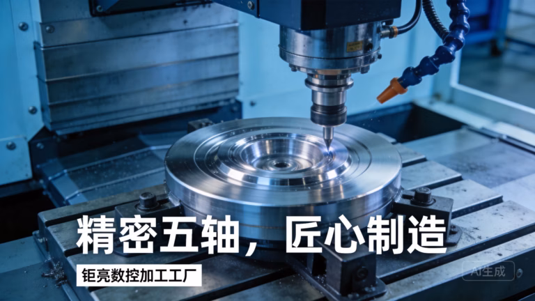
3. Multi-Axis Machining: For complex geometries, 5-axis CNC machining is employed. The cutting tool can move linearly along X, Y, and Z while the workpiece rotates on two additional axes (A and B). This allows the part to be approached from virtually any angle in a single setup, enabling the machining of intricate contours, undercuts, and angled features that would be impossible or require many setups on a 3-axis machine.
Phase 5: The Final Verification – Post-Processing and Quality Assurance
Once machining is complete, the part is not necessarily finished.
1. Secondary Operations: The part may require manual deburring (removing sharp edges), one-stop post-processing like sandblasting, anodizing (for aluminum), plating, painting, or heat treatment for enhanced material properties.
2. Final Quality Control (QC): The final part undergoes a comprehensive QC check. This is where a manufacturer’s commitment to standards like ISO 9001:2015 is proven. Documentation, including inspection reports and material certifications, is provided. For industries like automotive or medical, adherence to IATF 16949 or ISO 13485 adds layers of traceability and process control rigor.
3. Packaging and Delivery: Parts are carefully cleaned, protected, and packaged to prevent any damage during shipping.
Conclusion: It’s More Than Just a Machine
So, how do you CNC machine? You start with a meticulous design, translate it through expert programming, set it up with engineering precision, execute it with advanced technology and vigilant oversight, and verify it with unwavering quality standards. The true answer lies not in any single step, but in the seamless integration of all these phases by a skilled and experienced team. For businesses seeking reliability, precision, and a partner that navigates this complex process seamlessly, choosing a manufacturer with full-process chain integration, authoritative certifications, and deep engineering support is not just an option—it’s a strategic imperative for bringing high-quality, innovative products to market efficiently and reliably.
Frequently Asked Questions (FAQ)
Q1: What is the main advantage of 5-axis CNC machining over 3-axis?
A: The primary advantage is the ability to machine complex parts in a single setup. A 3-axis machine often requires multiple manual re-fixturings to access different sides, introducing potential alignment errors and increasing labor time. A 5-axis machine can rotate the part to present almost any angle to the tool, enabling faster production of intricate parts with higher accuracy and superior surface finishes on contoured geometries.
Q2: How do I know if my design is suitable for CNC machining?
A: Key indicators include: internal vertical corners will have a radius (equal to the tool radius), deep narrow cavities are challenging, very thin features may be fragile, and the part must be accessible by a cutting tool. The best practice is to engage in a Design for Manufacturability (DFM) review with your machining partner early in the design process.
Q3: What tolerances can I realistically expect from CNC machining?
A: Standard machining tolerances are around ±0.1 mm (±0.004″). High-precision machining can achieve tolerances of ±0.025 mm (±0.001″) or tighter on critical features. It’s crucial to specify tight tolerances only where functionally necessary, as each order-of-magnitude increase in precision significantly impacts cost and time.
Q4: How do you ensure the security and confidentiality of my design files?
A: Reputable manufacturers treat client IP with the utmost seriousness. Look for partners with systems compliant with ISO 27001 standards for information security. This involves secure file transfer protocols, access-controlled design servers, confidentiality agreements (NDAs), and strict internal data handling procedures.
Q5: What does “one-stop service” mean in CNC machining?
A: It means the manufacturer can handle the entire process beyond just cutting metal. This includes initial DFM consultation, material procurement, precision machining, secondary processes (like anodizing, heat treatment), comprehensive quality inspection, and final packaging/shipping. This streamlines procurement, reduces logistical complexity, ensures quality accountability, and accelerates overall project timelines.


