Click to learn:First hands-on 3D scanner tutorial: Installing the scanner
Click to learn:Third Hands-on 3D Scanner Tutorial: Collecting 3D Scan Data
1. Explanation of the concept of calibration
The built-in system of each scanner has a spatial coordinate. However, because the spatial coordinates in the machine will have errors after leaving the factory, and sometimes the spatial coordinates will differ according to the different sizes and positions of the scanned objects, so the calibration function is to succeed The calibration plate (positioning coordinates) is used to match spatial coordinates in the machine, unify spatial coordinates, or calibrate the user’s desired coordinate system.
2. Explanation of calibration steps
Connect the data cable – install the software – open the software – coarse adjustment – left camera focal length – right camera focal length – left aperture adjustment – right aperture adjustment – calibration
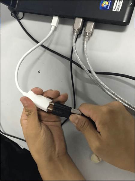
1. Connect the data cable


Note: After connecting to the computer, adjust the angle between the scanning head and the center support rod to approximately 10 to 15 degrees. Once the connection is successful, a blue light will be emitted.
2.Install the software

Install in one click
3. Open the software
1) Click on the installed software icon

2) Enter the interface

Note: After entering the page, if the left and right cameras are displayed in red as shown in the figure, it means that the distance between the scan head and the calibration plate is too close and the distance needs to be increased. As shown below


Let the red fade slowly

Color returns to normal
4. Coarse adjustment
Rough adjustment means a rough positioning test before preliminary calibration and debugging, and it is also a preliminary preparation for calibration.
1).Click coarse setting

2) Select the device model


3) Adjust the position of the scanning head to a vertical angle of approximately 20 degrees.


4) Place the calibration block on its side and set the distance between the measuring heads to approximately 670

5) Adjust the aperture of the network camera to make the cross frame projected on the calibration plate clearer.


It’s currently blurry and I can’t see the cross frame clearly.

Observe that the central cross gradually becomes lighter

Once debugging is complete, proceed to the next step
6) Set the left and right camera brightness value to “2”


Note: This is usually done outside the factory. If there are no special needs, no operation is required.

Click Finish
5. Left camera focal length
Camera focus refers to the clarity of the camera. Human eyes and cell phone cameras can automatically focus, but the scanner camera cannot, so you need to manually adjust the camera’s clarity to the appropriate position.
1) First place the calibration plate on its reverse side

2) Rotate the left camera’s focal length (sharpness) aperture to maximum


You will notice that the cross frame is very blurry
3) Adjust the brightness of the light machine to maximum


Click next
4) Slowly adjust the focus ring so that the cross frame changes from blurry to clear.


Make the Cross Clear
5) At the same time, during the adjustment process, you should pay attention to the ideal focus value and the deviation should not exceed plus or minus 1.


Click Finish
The focus of the left camera is the same as that of the right camera. Just follow the steps above to finish focusing the right camera.
6. Left aperture adjustment
Aperture adjustment refers to adjusting the brightness of the left and right cameras. There are two brightness levels in the scanner. One is the camera brightness of the software itself (can be adjusted in the software) and the other is the brightness of the left. and the right cameras themselves (can be adjusted by adjusting the left and right cameras rotating ring to adjust the appropriate brightness).
1). First set the camera’s exposure time to “2”.

You will find a red box indicating
2) Adjust the aperture to meet two conditions at the same time: the indicator image reaches green ok state, there is no red indication in the image area;


Once the setting is complete, click Next. The methods and guidelines for adjusting the left and right brightness are the same.
7. Setting the grating machine
The main function of this part is to accurately locate the position of the grating cross and the center point of the red cross of the left and right cameras, and adjust it to the best state through numerical values and clarity of observation with the naked eye. for further calibration.
1). First, make sure the array cross frame and the left and right camera red cross frame are almost aligned.

Note: Make sure the center point of the red cross of the left and right cameras is aligned with the center cross point frame of the grid.

Click next
2) Slowly adjust the grid ring to adjust the central grid frame to the clearest state

Note: The adjustment method is the same as left and right focus adjustment. Slowly rotate the network circle to make the central frame clear. At the same time, pay attention to the numerical changes of the ideal value and the current value. that the difference between the current value and the ideal value is not greater than plus or minus.” 1″ is enough


When the setting is completed, click “Finish”
8.Calibration
Calibration requires a total of 7 calibration drawings to determine the spatial size of the scanner. These 7 designs are used to ensure that the scanning task can be performed from all viewing angles. The seven calibration charts are: keep the original position unchanged, move up 30mm, move down 30mm, tilt the scanning head 10 degrees, tilt the scanning head 10 degrees to the right, raise the scan head 10 degrees forward and move the scan head. forward. Continue to raise it 10 degrees.
1) Click Calibration and select the machine model


2) Place the calibration plate (side with calibration points facing up)


3) Enter the screen as shown in the picture, calibrate the first picture first “Keep the position still”

Note: Theoretically, for the first image, the scan head should be adjusted to approximately a 10 degree angle with the center rod. However, because the angle was previously adjusted in the coarse adjustment step, the angle from the first image remains. unchanged. Just move.

4) After adjusting the position, click “Position”

Note: The calibration plate should be positioned correctly here (so that all the scanning light can be collected towards the calibration points of the calibration plate. At the same time, it should be noted that no debris is allowed on the calibration plate, otherwise there will be). will affect the calibration results.

There is debris on the calibration card

Note: If the above error occurs, the prompt in the image above will appear.
5) The second calibration table “Scan head rises from 30mm to 40mm”.

Note: Go up 30-40mm. Simply turn the handle clockwise 3-4 times


6) The third calibration table “Scan head lowered from 60mm to 70mm”

Note: Theoretically it is enough to drop from 30mm to 40mm, but since we have already increased from 30mm to 40mm before dropping, we go straight down from 60mm to 70mm here and turn the control lever clockwise. counterclockwise 6 to 7 times.

Click “Location” to complete 3
7) The fourth calibration chart “scan head tilted 10 degrees to the left”


8) The fifth calibration table “Scan head tilted 10 degrees to the right”


Note: After calibrating the left and right tilt angles, one thing you need to pay attention to here is to observe whether the left and right transverse centers of the camera in the center are still aligned with the array transverse frame. If it is not aligned, you must raise the scanner or adjust the position of the scanner to align it.

Place a piece of white paper in the center of the frame

Observe if the left and right cameras are aligned with the cross frame

Clearly not aligned

Lift the scanner with the lever

Complete alignment
Note: During the calibration process, it is not necessary to adjust the cross frame each time an image is calibrated. However, it should be noted that after tilting the scanner left and right, the cross frame will fundamentally deviate from a certain position.
9) The sixth calibration diagram “raise the scanning head 10 degrees forward”


Note: What we need to note here is that after increasing the angle of the scanner, its light will be refracted more, so some of the light may illuminate the outside of the calibration plate, so we need to move the position of the scanner to redirect all irradiated light onto the calibration plate.
10) The seventh calibration table “Continue to talk about the sweep head elevation of 10 degrees”


Calibration Summary:
Summary of steps:
This part mainly explains some preparations before starting scanning: rough processing – left camera focus – right camera focus – left aperture adjustment – right aperture adjustment – machine adjustment grid – calibration.
Summary of issues requiring attention:
Coarse adjustment is the overall placement of a machine position at the start. The machine is placed in a suitable position and the position of the cross frame of the grid is roughly determined. The focus of the left and right cameras is adjusted according to the sharpness of the left and right cameras to ensure the accuracy of subsequent data collection. Adjusting the left and right aperture is to adjust the brightness of the left and right cameras, echoing the brightness in the software, so that the brightness is adjusted to a suitable value for scanning. The adjustment of the grating machine is actually a more detailed and digital adjustment of the network cross frame on the basis of a coarse adjustment. The final step is calibration, which is to identify the calibration points on the calibration card based on 7 calibration images from different angles, meeting the user’s needs for multi -angle during the scanning process. Now that the preliminary preparation work is complete, you can begin scanning.
Daguang focuses on providing solutions such as precision CNC machining services (3-axis, 4-axis, 5-axis machining), CNC milling, 3D printing and rapid prototyping services.


