Click to learn:Mohou.com 3D scanning service at one price
Click to learn: Hands-on 3D Scanner Tutorial 2: Scanner Calibration
Click to learn: Hands-on 3D Scanner Tutorial 3: 3D Scanning to Collect Data
A,3DScanner Parts
OKL-E-400Scanner Parts Overview
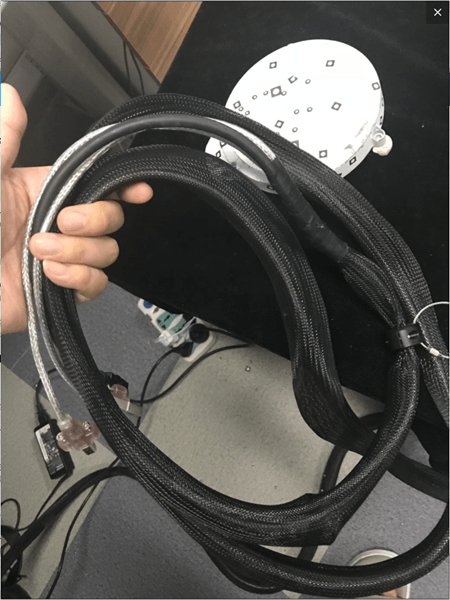
The photo scanner consists of four parts: the data cable, the control head, the tripod mount and the scanning component. Every piece is essential.
1.Data line part
A component that transfers data and connects the printer to the computer.

2.control header part
Use three control levers to control the orientation of the scanning head (height control, left and right tilt and horizontal rotation angle), making scanning more convenient.

3.Tripod part
The bracket intended to support the entire scanner is fixed by a three-point bracket to reduce jitter caused by external factors during scanning, thereby causing deviations in the accuracy of the scanned data.

4.Scan head part
Contains two eyepieces and a grating lens. The eyepiece collects the scanned data and the array lens transmits the data.

two,Steps to install the scanner
This section mainly explains how to install the photo scanner. Only after installation and confirmation of the hardware equipment can subsequent operations such as calibration and scanning be carried out. At the same time, when installing the scanner, care should be taken to preserve the scanner. three supports at the same level as possible. On the machine, the connection between the scan head and the control assembly must be solid. The specific operations are as follows
1.Installation support piece
The bracket is mainly used to fix the overall position of the scanner. This piece must be placed in a good position to keep all three supports at the same fulcrum, otherwise it will be difficult to adjust the height of the scan later.
1) First put the Delta support vertically

2) Loosen the elastic knob of the central rod


3) After loosening, grasp the brackets on both sides and pull the tripod bracket away. After opening it, do the reverse to tighten the center rod splint.


Tighten the center plate in the same way
4) Loosen the media lever and remove the growing media


5) The other two supports work as above. Place the bracket and tighten the knob to fix the height of the bracket while keeping the bracket parallel (otherwise there will be problems in subsequent scans).


At this point, the media installation is complete
2.Install the control head section
In this part of the control head, you should first pay attention to the threaded connection and fixing of the central hole and the triangular bracket. Second, master the functions of the three control rods in this part of the structure, which controls the height. , which controls left and right tilt, and which controls horizontal rotation.
1) Prepare the control head first

2) Install the push rod that controls the up and down angles onto the control head.


Tighten the push rod into the hole
3) Match the lower center hole of the control head to the upper screw of the tripod bracket, rotate the control head and fix the position.


4) Next, tighten the control head assembly and tripod mount by rotating the push rod horizontally (in case the previous step was not fully tightened)

5) Control head installation completed

3.Install the scan head assembly
The scanning head assembly includes: a fixed frame, two eyepieces (some camera models have four) and an array lens. The eyepiece collects data and the network generates data.
1) First prepare the playback head and look at the two mounting holes at the bottom.


2) Attach the large hole at the front end first. When screwing the large hole at the front end, be sure to fix the position first. You don’t need to tighten it all the way (it will be difficult to tighten the retaining screw at the front end). back if fully tightened).


3) Then fix the rear position


4) After attaching the piece of black card to the back, attach the piece of black card just reserved to the front.

4.Install the data cable
1) First hook the hook of the data cable to the scanner.


2) Connect the raster data cable


Just insert it directly
3)Insert the data cables of both lenses

Simply plug in the two pink data cables

4) The data line on the right works as above

5) Finally plug in the power cord

This completes the hardware installation steps for the machine.

3. Summary of 3D scanner component assembly:
Steps to organize:
Assembly sequence (bottom to top): install the delta bracket first——Repair the control head——Install the scanning component——Connect the data cable.
Summary of issues requiring attention:
For the delta bracket, you need to be careful to loosen the screws on the center pole first, fix the three brackets at a certain angle, and then tighten them (no more moving for now). When scaling the bracket, you should also pay attention to loosen the screws first, pull the bracket to a certain length, and then tighten the screws, otherwise the stretched bracket will be unstable. After determining the position, observe whether the bubble on the support is within the red circle. If not, readjust it. The connection between the control head and the data cable is very simple. Just pay attention to the alignment of the holes and tighten them. It is worth mentioning here that when attaching the control component and scanning component, you must first position the front hole successfully, and then position the rear hole (the front refers to the direction of the eyepiece and array lens), and when attaching both holes, the front hole only. You just need to attach the metal nut, leaving some room for the black clamp. If it is too tight, the holes on the back will be very inconvenient for alignment and installation. After securing the metal nut and black clip on the back, attach the black clip into the front hole. This completes the hardware installation. Next, let’s see how to calibrate the scanner once the hardware installation is complete.
Daguang focuses on providing solutions such as precision CNC machining services (3-axis, 4-axis, 5-axis machining), CNC milling, 3D printing and rapid prototyping services.


