There are many types of boring tools, how to choose?
❶ Annoying processing requirements.
❷ Boring processing method.
❸ Classification of boring tools.
❹ Boring tool CNC control application (coarse boring/fine boring).
1
Annoying processing requirements
Boring is one of the main processing contents of the machining center. It can accurately guarantee the dimensional accuracy and shape accuracy of the hole system and correct the errors of the previous process. Most of the cylindrical holes processed by reaming are the main mounting holes or supporting holes in machine parts, so they have high requirements for dimensional accuracy. Generally, the dimensional accuracy of mounting holes should be controlled at IT7~IT8, the dimensional accuracy of machine tool spindle box holes is IT6, and holes with lower precision requirements are generally controlled at IT11. For holes in brackets and sleeve parts that require greater precision, as well as large holes in box parts, the shape accuracy should be controlled to within 1/2 to 1/3 of the tolerance of the hole diameter. The drilling hole spacing error is generally controlled within ±0.025~0.06mm, and the parallelism error of the axis lines of the two holes is controlled within 0.03~0.10mm. The roughness of the bore surface is generally Ra1.6~0.4μm.
2
Boring processing method
The hole drilling process often goes through the processes of rough boring, semi-finished boring and fine boring. The choice of rough boring, semi-finished boring and fine boring processes depends on factors such as the accuracy requirements of the boring hole, the workpiece material and the specific structure of the workpiece.
01Single edge boring tool, rough boring
Rough boring is an important process for reaming cylindrical holes. It mainly preprocesses the rough hole (cast or forged hole) of the workpiece or the drilled or enlarged hole to prepare for the next step of semi-finished boring and fine boring. is necessary to lay the foundations and detect defects in the blank in time (cracks, sand inclusions, blisters, etc.). After rough boring, there is usually 2-3 mm left on one side as a margin for semi-finished boring and fine boring. For precision box parts, tempering or aging treatment should generally be arranged after rough boring to eliminate internal stress generated during rough boring, and finally fine boring should be carried out. Due to the large amount of cutting used in rough boring, the cutting force generated during rough boring is high, the cutting temperature is high, and the tool wear is large. In order to ensure the productivity of rough boring and a certain boring accuracy, it is necessary that the rough boring tool has sufficient strength, is able to withstand large cutting forces and has good shock resistance; a suitable geometric angle, to reduce the cutting force and facilitate heat dissipation of the boring tool.
02 Semi-precision bore
Semi-finished boring is a preparatory process for fine boring. It is mainly used to solve the uneven balance remaining during rough boring. For holes with high precision requirements, semi-finished boring is generally carried out in two steps: the first time is mainly to eliminate the uneven part left during rough boring; the second time consists of reaming the remaining excess thickness to improve the dimensional quality of the hole. , shape precision and reduced surface roughness. After semi-finished boring, the tolerance of fine boring is generally 0.3-0.4mm (single side). For holes that do not require high precision, fine boring can be performed directly after rough boring without the need for a semi-finished boring process.
03Precision boring
Fine boring is based on rough boring and semi boring, using higher cutting speed and smaller feed amount to cut off the small margin left by rough boring or semi boring. -end, in order to accurately meet the requirements specified in the interior drawing. surface of the hole. After rough boring, the clamping plate should be loosened and then tightened again to reduce the impact of clamping deformation on machining accuracy. Usually, the cutting quantity of fine bore is ≤0.01mm and the feed quantity is ≥0.05mm/r.
3
Classification of boring tools
Boring tools used in machining centers are not essentially different from cylindrical turning tools in terms of cutting parts. However, boring tools on machining centers generally use cantilever processing, so boring tools must be sufficiently rigid and relatively small. There are many types of boring tools to suit different cutting conditions. According to the number of cutting edges of boring tools, they can be divided into single-edged boring tools and double-edged boring tools.
01Single edge boring tool
Drilling of through and blind holes on boring machines

Drilling of through and blind holes on boring machines
The handle and the cutting part of this type of boring tool are integrated, and the cutting part is mainly made of carbide. Its structure is that illustrated in the figure. It only has one edge. It has compact and simple structure, small size, easy manufacturing and wide application. It can drill all kinds of small holes, closed holes and step holes. If installed on a universal tool holder or rotating flat sliding disc, it can drill larger diameter holes and end faces. However, the single-edge boring tool has poor rigidity and is prone to vibration during cutting. Therefore, the main angle of the boring tool is chosen to be larger to reduce the radial force. The size of the bore hole diameter should be ensured by adjusting the tool overhang length. Adjustment is difficult and has low efficiency. It can only be used for single piece and small batch production.
02Refined boring tool

1 Washer 2 Clamping screw 3 Boring bar 4 Adjusting nut 5 Insert 6 Boring head 7 Guide chain
As shown in the figure, this boring tool is suitable for fine adjustment of boring tools on automatic lines, coordinate boring machines and CNC machine tools. It has the characteristics of simple structure, easy manufacturing, convenient adjustment and high precision. The adjusting nut and the boring tool head are pressed against the boring bar by the set screw and washer. When adjusting, loosen the set screw slightly and turn the adjustment nut with scale to fine-tune the boring tool, then tighten it.
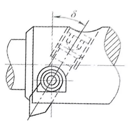
03Floating boring tool

① How is the floating boring tool represented? Its characteristics are as follows: The floating boring tool is installed in the square hole of the boring bar. It can automatically balance and center its cutting position by the cutting force on the cutting edges. on both sides, so there is no need for clamping, and can also automatically compensate for machining errors caused by boring tool installation errors, radial circular runout of bar bore or deflection of the machine tool spindle, thereby eliminating machining errors caused by radial effect. force on the boring bar during boring.
② The processing accuracy can reach IT7-IT6. The Ra cast iron hole can be processed to 0.8-0.2 μm, and the steel hole can be processed to 1.6-0.4 μm.
③ Since the linear error and hole position error cannot be corrected, the prefabricated hole should have good linearity and surface roughness value Ra≤0.4μm.
④ It has a simple structure and is easy to sharpen, but it is inconvenient to use and cannot process holes with too small openings. It also has high manufacturing requirements for boring tools and boring bars, especially for processing square holes on boring bars. the cutting efficiency is lower than that of boring.
04Clamp Type Deep Hole Reaming Tool

Machine Collet Indexable Carbide Deep Hole Boring Tool
1 Adjust inclined iron 2 Knife wedge 3 Indexable blade 4 Guide block 5 Knife body
6 Adjustment screw 7 Blade shoe set screw 8 Guide block set screw
This type of boring tool has the common characteristics of deep hole tools in terms of structure, including a guide block, chip discharge hole or cutting fluid inlet hole. Machine clamped deep hole boring tools are divided into machine clamped indexable deep hole boring tools and mechanically clamped deep hole boring tools. The structures of the two are similar, but the blades and tool pads are clamped differently. The first is easy to use and the second has good rigidity. The picture shows the machine clamping indexable carbide deep hole boring tool. The guide block is welded by the guide shoe and the carbide guide block, and is clamped on the boring tool body with screws. Secure the indexable insert on the tool wedge to the boring tool body using screws. Turn the adjusting screw to drive the adjusting inclined iron to move axially, and the radial size of the boring tool can be adjusted.
05 Modular boring tool
 In order to adapt to the needs of different hole diameters and depths and reduce the variety and specifications of boring tools, a modular boring tool is designed. Modular boring tool divides the boring tool into several parts: base shank, extension, reducer, boring bar, boring head, insert seat, insert, etc., and then freely combine them into depending on the specific treatment content. This not only greatly reduces the number of tool holders and saves costs, but also can quickly meet various processing requirements and extend the overall tool life. Clearly, modular boring tools have advantages that integrated boring tools cannot match. Of course, this also requires that modular boring tools have high continuous precision and high continuous rigidity, as well as high repeatability and high reliability. In short, the modular boring tool system has great advantages, but that doesn’t mean it only has to be modular. It needs to be measured in many aspects such as connection stiffness, accuracy, operability, price, etc.
4
Boring tool cycle control
Roughing tool cycle control
Rough boring cycle instructions: G85, G86, G88, G89
Format of instructions:
G85 X_Y_Z_R_F_ ;
G86 X_Y_Z_R_F_P_ ;
G88 X_Y_Z_R_P_F_ ;
G89 X_Y_Z_R_P_F_ ;
The G85 cycle tool processes to the bottom of the hole in cutting feed mode, then returns to cutting feed mode.
The G86 cycle tool processes to the bottom of the hole in cutting feed mode, the spindle stops and the spindle rotates forward after the tool quickly returns to the R plane (used for drilling holes with low precision).
G89 and G85 are basically the same. The difference is that G89 adds a pause when processing to the bottom of the hole (commonly used for processing step holes).
The G88 cycle tool processes to the bottom of the hole in cutting feed mode. After the tool pauses at the bottom of the hole, the spindle stops, then manually retracts the tool, then starts automatic processing. R plane/initial plane, and the spindle resumes its forward rotation.


Fine boring tool cycle control
G76 fine boring cycle and G87 reverse boring cycle
Format of instructions:
G76 X_Y_Z_R_Q_P_F ;
G87 X_Y_Z_R_Q_F ;
G76 is used for precision boring processing. The tool cuts to the bottom of the hole to achieve a precise spindle stop. The tool moves Q in the direction opposite the tool tip so that the tool leaves the surface of the workpiece. scratch the workpiece surface, then quickly retract to the R reference plane or the initial plane, the spindle rotates forward.
After G87 is positioned in the G17 plane, the spindle stops precisely, the tool moves Q in the direction opposite the tool tip, and then moves quickly to the bottom of the hole. Then the tool moves Q in the original direction, the spindle. rotates forward and processes the upper part in cutting mode, and the spindle is precise again. Stop, move Q in the opposite direction along the tool tip, quickly lift the tool to the R plane or the original plane, then return to G17 positioning. point, and the spindle rotates forward.


5
Installation and adjustment
① Installation instructions (small diameter boring tool)
1. Screw the boring head into the boring bar.
2. Loosen the boring bar lock screw on the fine boring head.
3. Insert the boring bar and reducing sleeve (if equipped) so that the notch on the reducing sleeve is at a 90 degree angle to the boring bar locking screw. Note: Do not use flattened boring bars.
4. Rotate the boring bar so that the tip of the blade lines up with the mark on the top of the fine boring tool. The tip of the tool should be slightly above the mark for best reaming results.
5. Adjust the boring bar to the shortest extension required.
6. Tighten the boring bar radial locking screw, maximum torque 1.13 Nm
How to install →


② Adjustment of boring head
1. Loosen the radial locking screw.
2. Adjust the bore hole diameter by rotating and reading the scale value on the dial. Each time the scale on the scale increases by one division, the bore hole diameter increases by 0.02 mm. adjustments of 0.002 mm per division.
3. Tighten the radial locking screw with a maximum torque of 1.13 Nm.
Boring head adjustment →


✴The instructions above are for reference only and are not universal standards✴
Daguang focuses on providing solutions such as precision CNC machining services (3-axis, 4-axis, 5-axis machining), CNC milling, 3D printing and rapid prototyping services.


