127 Sets Processing 4000mm 127 Sets High-Precision CNC Lathes
15 Years of Experience

CNC Knowledge: Downmilling or upmilling, how to choose?

Milling cutters are generally multi-edged tools. Because they have many teeth involved in cutting at the same time, have long cutting edges, and can use higher cutting speeds, they have high productivity. Different cutters can be used to process planes, grooves, steps, etc., as well as gears, threads, splined shaft tooth shapes and various formed […]

cnc knowledge: downmilling or upmilling, how to choose?

Milling cutters are generally multi-edged tools. Because they have many teeth involved in cutting at the same time, have long cutting edges, and can use higher cutting speeds, they have high productivity. Different cutters can be used to process planes, grooves, steps, etc., as well as gears, threads, splined shaft tooth shapes and various formed surfaces.

1

Structure of the cutter

Let’s take the example of indexable cutters:

1) Main geometric angles

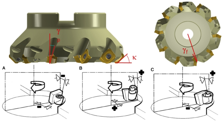
The milling cutter has a lead angle and two rake angles, one is called axial rake angle and the other is called radial rake angle.

The radial rake angle γf and the axial rake angle γp. The radial cutting angle γf mainly affects the cutting power; the axial rake angle γp affects the chip formation and the direction of the axial force. When γp is a positive value, the chips. fly away from the noodle machining process.

Cutting angle (contact surface of cutting face)

Negative cutting angle: for steel, steel alloys, stainless steel, cast iron.

Positive rake angle: used in viscous materials and some high temperature alloys.

Center front corner: used for threading, grooving, profiling and forming knives.

1688370022775726.jpg

Use negative cutting angles whenever possible.

2) Cutter geometry

The first is: positive angle – positive angle

1688370042166756.jpg

The cut is light and smooth, but the edge strength is poor. Suitable for processing soft materials and stainless steel, heat-resistant steel, ordinary steel and cast iron, etc. This shape should be preferred in the presence of low-power machine tools, insufficient rigidity of the process system and built-up edges.

Benefits :

+ soft fit

+ Smooth chip evacuation

+ good surface roughness

Disadvantages:

– Peak strength

– Does not promote switching off the contact

– The workpiece is separated from the machine table

Next comes: negative angle – negative angle

1688370071452594.jpg

It has strong impact resistance and uses negative blades, suitable for rough milling of cast steel, cast iron and high hardness and high strength steel.

However, milling consumes a lot of energy and requires excellent rigidity of the process system.

Benefits :

+ peak force

+ Productivity

+ Push the part towards the machine table

Disadvantages:

– Greater cutting force

– Chip blocking

Finally: positive angle – negative angle

1688370086969458.jpg

The cutting edge has strong impact resistance and is sharp. Suitable for processing steel, cast iron and cast iron. The effect is also better when milling with large margins

Benefits :

+ Smooth chip evacuation

+ favorable cutting forces

+Wide range of applications

3) No strawberries

1688370102277072.jpg

1688370166792702.jpg

1) Dense teeth: high speed feeding, large milling force, small chip space.

2) Standard teeth: conventional feed speed, milling force and chip gap.

3) Coarse teeth: low speed feed, low milling force, large space for chips.

If the cutter is not equipped with a special Wiper insert, the surface roughness depends on whether the feed per revolution exceeds the width of the Wiper plane of the insert.

Example: groove milling and contour milling

Photo WeChat_20230703153853.jpg

Number of teeth:

•Sparse or standard teeth for milling grooves (safety)

•Dense teeth for contour milling (productivity)

2

Types and Uses of Strawberries

Types of cutters can be divided into sharp-toothed cutters and shovel-toothed cutters according to the structure of the teeth. According to the relative position of the cutter teeth and the axis of the cutter, it can be divided into cylindrical cutters, angle cutters, face cutters, forming cutters, etc. According to the shape of the teeth of the milling cutter, they can be divided into straight tooth milling cutters, spiral tooth milling cutters, angle tooth milling cutters and curved tooth milling cutters. According to the structure of the tool, it can be divided into integral cutters, combination cutters, groups or complete sets of cutters, insert tooth cutters, machine collet welding cutters, indexable cutters, etc. But it is generally divided into the form of teeth back processing of cutting tools.

Photo WeChat_20230703153856.jpg

Sharp tooth cutters can be divided into the following types:

(1) Face milling cutters include solid face milling cutters, toothed face milling cutters, machine clamped indexable face milling cutters, etc., which are used for roughing, semi-finishing and finishing of various planes , walking surfaces, etc.

(2) End mills are used for milling walking surfaces, side surfaces, groove recesses, holes of various shapes on the workpiece and internal and external curved surfaces, etc. While end mills are easily distinguished, they can be divided into two categories: left-handed and right-handed. Nowadays, many people still have no concept of left and right rotation.

Right hand cutter

First, the following method can be used to determine whether the tool is left-handed or right-handed. Faced with a vertically placed cutter, if the flute rises from the bottom left to the top right, it is a right rotation; if the flute rises from the bottom right to the top left, it is a left rotation. You can also use the right hand rule for right rotation. The four bent fingers indicate the direction of rotation and the raised thumb indicates the direction up, which indicates rotation to the right. The spiral flute plays a chip retaining role and is also the part that makes up the cutting angle and the front face of the cutter.

WeChat photo_20230703153859.gif

Left cutter

Left-handed cutters are generally chosen for high precision machining requirements. Left-handed milling cutters are generally used in the finishing processing of mobile phone buttons, membrane switch panels, LCD panels, acrylic lenses, etc. But there are some demanding ones, including the production and processing of some mobile phone buttons or electrical appliance panels. The requirements for high precision and smooth finishing are also very high. You need to choose the bottom row of cutout and turn left. avoid knife edge whitening and processing. Incisions on parts may appear, etc.

Photo WeChat_20230703153902.jpg

(4) Groove cutter and saw blade cutter are used for milling various grooves, sides, walking surfaces and sawing, etc.

(5) Special groove cutters are used for milling various shapes of special grooves, such as shaped groove cutters, half-moon groove cutters, dovetail groove cutters, etc.

(6) Angle milling cutter: used for milling straight grooves, spiral grooves, etc.

(7) Mold milling cutter: used for milling the convex and concave forming surfaces of various molds.

(8) Group milling cutter: multiple milling cutters are combined into a set of milling cutters, which are used for milling complex forming surfaces, surfaces of different parts of large parts and wide planes.

Shovel tooth cutters: Some cutters that require resharpening the front and back to maintain the original tangential shape and use shovel teeth on the back, including disc slot cutters, spade tooth cutters, convex semicircle, concave semicircle cutters, double angle cutters, and form cutters, knife, etc.

3

Milling down and milling up

There are two methods relating to the direction of feed of the part and the direction of rotation of the cutter:

1688370273771132.jpg

The first is uphill milling. The direction of rotation of the cutter is the same as the direction of feed of the cut. When cutting begins, the cutter bites the workpiece and cuts the final chips.

1688370296896106.jpg

Down milling

The second type is upward milling. The direction of rotation of the cutter is opposite to the direction of cutting feed. The cutter should slide over the workpiece for a while before starting to cut. with the maximum cutting thickness.

1688370325155902.jpg

Ascending milling

In three-sided milling cutters, some end mills or face milling cutters, the cutting forces have different directions. When facing, the cutter is just outside the workpiece, so special attention must be paid to the direction of the cutting force. When milling down, the cutting force pushes the workpiece toward the workbench; when milling up, the cutting force pushes the workpiece away from the workbench.

Since the cutting effect of down milling is the best, down milling is generally preferred. Only when the machine tool has thread clearance problems or problems that cannot be solved by down milling is up milling considered. Ideally, the diameter of the cutter should be larger than the width of the workpiece and the axis of the cutter should always be slightly away from the axis of the workpiece. When the tool is placed directly against the cutting center, burrs are easily generated.

The direction of the radial cutting force will continue to change as the cutting edge enters and exits the cut. The machine tool spindle may vibrate and be damaged. The blade may be broken and the machined surface will be very rough. off-center, the direction of the cutting force will no longer fluctuate – The cutter will receive a preload. We can compare center milling to driving down the center of the road.

Each time a milling insert enters a cut, the cutting edge is subjected to impact loads whose magnitude depends on the cross-sectional area of ​​the chip, the workpiece material and the type of cut . When cutting and removing, the correct engagement between the cutting edge and the workpiece is an important direction.

When the cutter axis is completely outside the width of the workpiece, the impact force during cutting is borne by the outermost tip of the insert, which means that the initial impact load is borne by the most sensitive part of the tool. The cutter finally leaves the workpiece with its tip, which means that from the start of the cut until the blade leaves, the cutting force acts on the outermost tip until the impact force is discharged.

When the center line of the cutter is exactly on the edge line of the workpiece, the blade will break away from the cut when the chip thickness reaches the maximum and the impact load reaches the maximum when cutting . When the cutter axis is within the width of the workpiece, the initial impact load during cutting is borne by the part farthest from the most sensitive tool tip along the cutting edge, and the blade comes out of the cut relatively smoothly when it retracts.

For each insert, it is important how the cutting edge leaves the part upon exiting the cut. Material remaining near retraction can reduce blade play somewhat. As the chip breaks away from the workpiece, an instantaneous pulling force is generated along the rake face of the blade and often produces burrs on the workpiece. This pulling force can endanger the chip edge in dangerous situations.

Comparison table between down milling and up milling

Photo WeChat_20230703153914.jpg

Daguang focuses on providing solutions such as precision CNC machining services (3-axis, 4-axis, 5-axis machining), CNC milling, 3D printing and rapid prototyping services.

CNC Experts

Picture of JinShui Chen

JinShui Chen

Rapid Prototyping & Rapid Manufacturing Expert

Specialize in CNC machining, 3D printing, urethane casting, rapid tooling, injection molding, metal casting, sheet metal and extrusion

CNC Recent Posts

CNC News

Welcome to GreatLight Metal,Maximum Processing Size 4,000 mm

Precision Machining CNC Quote Online

Loading file

Upload Click here to upload or drag and drop your model to the canvas.

The model is too large and has been resized to fit in the printer's build tray. [Hide]

The model is too large to fit in the printer's build tray. [Hide]

The model is too large, a fitting printer is selected. [Hide]

The model is too small and has been upscaled. [Hide]

Warning: The selected printer can not print in full color [Hide]

Warning: obj models with multiple meshes are not yet supported [Hide]

Warning: Unsupported DXF entity  [Hide]

Warning: could not arrange models [Hide]

[Hide]


File Unit:      
Scale:
%
L × W × H:
X: × Y: × Z:  cm 
Rotation:
X: ° Y: °  
⚡ Instant Quote for Precision Manufacturing

Submit your design files (STEP/IGES/DWG) and receive a competitive quote within 1 hour, backed by ISO 9001-certified quality assurance.

📋 How It Works

  1. Upload & SpecifyShare your 3D model and select materials (Aluminum/Stainless Steel/Titanium/PEEK), tolerances (±0.002mm), and surface treatments.

  2. AI-Powered AnalysisOur system calculates optimal machining strategy and cost based on 10+ years of automotive/aerospace data.

  3. Review & ConfirmGet a detailed breakdown including:
    - Volume pricing tiers (1-10,000+ units)
    - Lead time (3-7 days standard)
    - DFM feedback for cost optimization

Unit Price: 

Loading price
5 Axis CNC Machining Equipment
4 Axis CNC Machining Equipment
3 Axis CNC Machining Equipment
CNC Milling & Turning Equipment
Prototype and Short-Run Injection Moldings Exact plastic material as final design
Volume Metal Die Casting Services - Precision Cast Parts
Bridge the Gap From Prototype to Production – Global delivery in 10 days or less
Custom high-precision sheet metal prototypes and parts, as fast as 5 days.
Custom Online 3D Printing Services
Design Best Processing Method According To 3D Drawings
Alloys Aluminum 6061, 6061-T6 Aluminum 2024 Aluminum 5052 Aluminum 5083 Aluminum 6063 Aluminum 6082 Aluminum 7075, 7075-T6 Aluminum ADC12 (A380)
Alloys Brass C27400 Brass C28000 Brass C36000
Alloys Stainless Steel SUS201 Stainless Steel SUS303 Stainless Steel SUS 304 Stainless Steel SUS316 Stainless Steel SUS316L Stainless Steel SUS420 Stainless Steel SUS430 Stainless Steel SUS431 Stainless Steel SUS440C Stainless Steel SUS630/17-4PH Stainless Steel AISI 304
Inconel718
Carbon Fiber
Tool Steel
Mold Steel
Alloys Titanium Alloy TA1 Titanium Alloy TA2 Titanium Alloy TC4/Ti-6Al 4V
Alloys Steel 1018, 1020, 1025, 1045, 1215, 4130, 4140, 4340, 5140, A36 Die steel Alloy steel Chisel tool steel Spring steel High speed steel Cold rolled steel Bearing steel SPCC
Alloys Copper C101(T2) Copper C103(T1) Copper C103(TU2) Copper C110(TU0) Beryllium Copper
Alloys Magnesium Alloy AZ31B Magnesium Alloy AZ91D
Low Carbon Steel
Alloys Magnesium Alloy AZ31B Magnesium Alloy AZ91D
ABS Beige(Natural) ABS Black ABS Black Antistatic ABS Milky White ABS+PC Black ABS+PC White
PC Black PC Transparent PC White PC Yellowish White PC+GF30 Black
PMMA Black PMMA Transparent PMMA White
PA(Nylon) Blue PA6 (Nylon)+GF15 Black PA6 (Nylon)+GF30 Black PA66 (Nylon) Beige(Natural) PA66 (Nylon) Black
PE Black PE White
PEEK Beige(Natural) PEEK Black
PP Black PP White PP+GF30 Black
HDPE Black HDPE White
HIPS Board White
LDPE White
This is a finish of applying powdered paint to the components and then baking it in an oven, which results in a stronger, more wear- and corrosion-resistant layer that is more durable than traditional painting methods.
No coating required, product’s natural color!
This is a finish of applying powdered paint to the components and then baking it in an oven, which results in a stronger, more wear- and corrosion-resistant layer that is more durable than traditional painting methods.
This finishing option with the shortest turnaround time. Parts have visible tool marks and potentially sharp edges and burrs, which can be removed upon request.
Sand blasting uses pressurized sand or other media to clean and texture the surface, creating a uniform, matte finish.
Polishing is the process of creating a smooth and shiny surface by rubbing it or by applying a chemical treatmen
A brushed finish creates a unidirectional satin texture, reducing the visibility of marks and scratches on the surface.
Anodizing increases corrosion resistance and wear properties, while allowing for color dyeing, ideal for aluminum parts.
Black oxide is a conversion coating that is used on steels to improve corrosion resistance and minimize light reflection.
Electroplating bonds a thin metal layer onto parts, improving wear resistance, corrosion resistance, and surface conductivity.
This is a finish of applying powdered paint to the components and then baking it in an oven, which results in a stronger, more wear- and corrosion-resistant layer that is more durable than traditional painting methods.
Please provide additional text description for other surface treatment requirements!
Material
Material
  • CNC Metals
    • Aluminum
    • Brass
    • Stainless steel
    • Inconel718
    • Carbon Fiber
    • Tool Steel
    • Mold Steel
    • Titanium
    • Alloy Steel
    • Copper
    • Bronze
    • Low Carbon Steel
    • Magnesium
  • CNC Plastics
    • ABS
    • PC
    • PMMA (Acrylic)
    • PA (Nylon)
    • PE
    • PEEK
    • PP
    • HDPE
    • HIPS
    • LDPE
Printer
Printer
  • CNC Metals
    • 5 Axis CNC Machining
    • 4 Axis CNC Machining
    • 3 Axis CNC Machining
    • CNC Milling & Turning
    • Rapid Tooling
    • Metal Die Casting
    • Vacuum Casting
    • Sheet Metal Fabrication
    • SLA 3D Printing
    • SLS 3D Printing
    • SLM 3D Printing
  • Rapid Prototyping
    • Design Best Processing Method According To 3D Drawings
Post-processing
Post-processing
  • As Machined(Product’s natural color)
  • Sand Blasting
  • Polishing
  • Brushed Finish
  • Anodizing
  • Black Oxide
  • Electroplating
  • Paint Coating
  • Powder Coating
  • Other surface treatment requirements
Finalize
The world's first CNC machining center that dares to provide free samples!

Free for first product valued at less than $200. (Background check required)

precision machining cnc quote online

15 Years CNC Machining Services

When you’re ready to start your next project, simply upload your 3D CAD design files, and our engineers will get back to you with a quote as soon as possible.
Scroll to Top

ISO 9001 Certificate

ISO 9001 is defined as the internationally recognized standard for Quality Management Systems (QMS). It is by far the most mature quality framework in the world. More than 1 million certificates were issued to organizations in 178 countries. ISO 9001 sets standards not only for the quality management system, but also for the overall management system. It helps organizations achieve success by improving customer satisfaction, employee motivation, and continuous improvement. * The ISO certificate is issued in the name of FS.com LIMITED and applied to all the products sold on FS website.

greatlight metal iso 9001 certification successfully renewed
GB T 19001-2016 IS09001-2015
✅ iso 9001:2015
greatlight metal iso 9001 certification successfully renewed zh

IATF 16949 certificate

IATF 16949 is an internationally recognized Quality Management System (QMS) standard specifically for the automotive industry and engine hardware parts production quality management system certification. It is based on ISO 9001 and adds specific requirements related to the production and service of automotive and engine hardware parts. Its goal is to improve quality, streamline processes, and reduce variation and waste in the automotive and engine hardware parts supply chain.

automotive industry quality management system certification 01
Certification of Production Quality Management System for Engine Hardware Parts Engine Hardware Associated Parts
automotive industry quality management system certification 00
发动机五金零配件的生产质量管理体系认证

ISO 27001 certificate

ISO/IEC 27001 is an international standard for managing and processing information security. This standard is jointly developed by the International Organization for Standardization (ISO) and the International Electrotechnical Commission (IEC). It sets out requirements for establishing, implementing, maintaining, and continually improving an information security management system (ISMS). Ensuring the confidentiality, integrity, and availability of organizational information assets, obtaining an ISO 27001 certificate means that the enterprise has passed the audit conducted by a certification body, proving that its information security management system has met the requirements of the international standard.

greatlight metal technology co., ltd has obtained multiple certifications (1)
greatlight metal technology co., ltd has obtained multiple certifications (2)

ISO 13485 certificate

ISO 13485 is an internationally recognized standard for Quality Management Systems (QMS) specifically tailored for the medical device industry. It outlines the requirements for organizations involved in the design, development, production, installation, and servicing of medical devices, ensuring they consistently meet regulatory requirements and customer needs. Essentially, it's a framework for medical device companies to build and maintain robust QMS processes, ultimately enhancing patient safety and device quality.

greatlight metal technology co., ltd has obtained multiple certifications (3)
greatlight metal technology co., ltd has obtained multiple certifications (4)

Get The Best Price

Send drawings and detailed requirements via Email:[email protected]
Or Fill Out The Contact Form Below:

All uploads are secure and confidential.