1. Introduction
With the rapid development of industrial technology, CNC machine tools have evolved from original single-function processing equipment to diversified compound processing equipment. Multifunctional turning, milling and boring machine tools have become the mainstream of machine tool design and manufacturing in recent years. They are mainly divided into:
1. Based on the host structure of small and medium-sized machine tools, a series of products that combine turning, milling and boring with multiple types of processing. The characteristics of this type of products are high processing efficiency with automatic feeders and black light plants. can be achieved.
2. Compound processing equipment based on the main structure of a large machine tool and capable of processing turning, milling, boring and grinding gears. This type of equipment has a complex structure, many components, strong composition and high precision, which highlights. very high design and manufacturing requirements. Large-scale manufacturers at home and abroad are adopting modular design concepts to meet the design and manufacturing requirements of large-scale composite machine tools.
2. The meaning of modular design
The meaning of modular design is to divide and design a series of modules and form different products through the selection and combination of modules to meet different market needs. Module is “a group of units that have the same function and combination elements (referring to the shape and size of the connecting parts and the matching parameters between the connecting parts, etc.), but have different uses (or performances) and structures and are interchangeable (parts, assemblies, subassemblies or systems), or units that increase the functionality of a machine tool.” The modular design method is not limited to metal cutting machine tools, but can also be applied to emerging machine fields such as sand cutting and wafer cutting.
Different combinations of modules can be used to form a single machine tool with different requirements, and can also be combined into a production line. For example, gantry machine tools can be combined with rotary table modules, rotating head modules, vertical grinding head modules, etc. cutting head modules, etc. Turning, grinding, gear hobbing and other processing.
3. Features of modular design
Modular design differs from traditional design mainly in its modular structure and reconfigurability, that is, it can adjust its processing functions and certain performances through the reorganization and replacement of components or machine modules -tools, so as to meet the requirements of machine tools in a quick and efficient manner. The various changing needs of parts also provide an efficient way to reuse machine tool components multiple times during their life cycle, thereby maximizing the savings and efficiency of equipment modifications and upgrades. The essence of machine tool modularization is based on geometric and physical similarities. It also considers the topology of geometric/physical similarities and generalized similarity based on the concept of combined topology, and introduces the extremely important concept of integrating module and interface characteristics to realize the “multiplier effect” of the integration of modules. The goal of the design is to make the machine tool, as a manufacturing resource, combined and flexible in its functions and performance throughout its life cycle, and to make the design and manufacturing green and economical .
Applying the concept of interface integration is to make modules more interchangeable, which requires that the structural elements between modules and connectors are consistent. The concept of interface integration is simplest to implement in the variants of the horizontal machine tool series (similar products), but it can also be implemented for the entire product range ( products of different specifications, composite machine tools) provided that the basic functions are the same and the motion parameters and power parameters are equivalent. Interface integration of modules, especially of some independent functional units, such as spindle system or auxiliary system modules, facilitates the realization of interface integration between modules.
4. Key technologies of modular design
1. Division of modules
The division of machine tool modules is a key issue in the modular design of machine tools. For conventional large metal cutting machine tools (turning, milling, grinding, boring, gear hobbing) and other similar processing equipment, the modules can be divided into: conventional mechanical modules, general intelligence There are four categories: modules, electrical control modules and auxiliary function modules.
Conventional mechanical modules are divided into 12 categories, including: bed and feed module, linear motion table module, sliding module, vertical rotary motion table module (turntable or rotary table), motion table modules horizontal rotary (headstock and tailstock), column modules, beam and feed system modules, and basic functional modules. The basic functional modules include slide module and feed system module, boring and milling module, turning module, grinding module and gear hobbing module. General intelligent modules are generally more advanced machine vision, intelligent sensing, machine tool working status monitoring and other modules. These modules generally use mature products made by professional manufacturers and are used with CNC system modules. Auxiliary modules are generally mature auxiliary equipment such as chip conveyors and automatic feeders, which can be selected according to needs.
2. Module design method
Conventional mechanical modules are the core of modular design, and each module has unique characteristics and design difficulties. The next section focuses on typical module design methods.
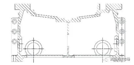
The bed and power module mainly constitute the bed part of the machine tool, which forms the basis of the entire machine tool. This is an important guarantee for the machine tool to have sufficient rigidity and precision when moving the main components of the machine. cutting tool and process. Large machine tool benches and feed modules generally consider three fundamental factors: the first is load capacity, the second is the length of a single part, and the third is the selection of the feed system. The load capacity mainly depends on the number of guide rails of the bed module, the width of the guide rails and the overall cross section of the bed. Design and planning must be realistic and forward-looking, as well as the commonalities of several. types of large machine tool beds need to be integrated into the overall design, such as: gantry mobile boring and milling machines, single column mobile vertical lathes, and pedestal boring and milling machines are all universal in their bed modules and can be coordinated during planning and design. Large machine tool beds are generally designed in segments. Although the length of individual parts meets the priority of the sequence, they can be designed according to the blank molding capacity and the processing capacity of the parts, and combined into the required length according to the needs of the user. In terms of power systems, with the widespread application of planetary gear reducers, the dual-motor rack and pinion drive technology that eliminates backlash simplifies the design of linear axis feed movement and creates conditions for the application of a modular design. The bed module basically adopts two categories: welding of cast iron or steel plates. The cast iron bed generally adopts HT250 gray cast iron. This type of cast iron has high compressive strength, excellent wear resistance and vibration absorption, low notch sensitivity and is suitable. for machine tool benches subject to pressure and vibration. As shown in Figures 1, 2 and 3.
Figure 1 Sectional view of a small bed

Figure 2 Sectional view of an average sized bed

Figure 3 Sectional view of a large bed
Vertical rotary worktable modules can be divided into two types: main movement type and feed movement type. The main movement type is usually a rotating worktable used in vertical lathes, and its design idea is similar to that of the bed module. The feed type of motion is used in floor boring and milling machines and gear hobbing machines. The main difference is that the shape of the working surface of the two is different. The floor boring machine and milling machine are rectangular, while the floor milling machine is rectangular. the machine is circular. Although the appearance is different, the modular design concept can also be applied to rotation system, base system, positioning system, etc.
The column module is mainly used in three types of machine tools: gantry boring and milling machines, vertical lathes, and floor-standing boring and milling machines When designing, refer to the design ideas of the bed module to determine the shape of the guide rail. span, section and other elements. At the same time, it can be used when casting or welding the blank. By applying the modular design concept, casting patterns and sand cores are produced in units of 500mm length to ensure the part length required by the. the user can be quickly realized. As shown in Figures 4 and 5.

Figure 4 Cross-section of small columns Figure 5 Cross-section of medium-sized columns
The traverse module is the core component of the gantry milling machine and vertical lathe. It is particularly important for planning the modular design of the cross section. The shape of the guide rail, the span, the position of the power system, etc. must be designed accordingly. the different loads of the sleepers. As shown in Figures 6 and 7.

Figure 6 Cross-sectional view of small beams Figure 7 Cross-sectional view of medium-sized beams
The basic functional module is the key design link of various machine tools. The sliding module is the connection point between the beam and the milling module, turning module and grinding module. The design of the sliding module mainly considers the connection with various functional modules and should be adjusted according to actual needs.
Milling, turning, grinding and gear hobbing modules should be designed based on the basic functional requirements of the machine tool. For example, in a compound machine tool, where the milling function is the main turning function and is supplemented by the turning function, a turning accessory head module can be added to the boring head module and milling tool to extend the turning function. If turning is the primary task and milling is completed, a milling accessory head is added to the turning head. In addition, in recent years, internationally renowned manufacturers have developed gear hobbing processing modules suitable for use in compound gantry turning and milling machine tools. The functional modules for processing ultra-large ring gears are supplemented by milling head modules, turntable modules and gear hobbing. modules. The concept of modular design should be implemented in the design process of basic functional modules. For example, in the design of the milling module spindle assembly, among the bearing arrangements that achieve the same load and speed, priority should be given to the arrangement. which can fit the same series of milling modules.
3. Application of modular design
Modular design applications are mainly divided into horizontal series applications, full series applications and full life cycle applications.
(1) Modular design and horizontal series application
Horizontal series modular design refers to the use of modifications and combinations of modules to develop variants of machine tools without changing the main parameters of the machine tool. This method is the most widely used. It mainly uses the method of replacing or adding modules to form many variations based on the base variety. For example, the most common small horizontal turn-mill machine tool is a typical application.
(2) Modular design for a full range of applications
This type of modular design involves many factors and is relatively complex. It is mainly used to combine functional modules into cross-series products according to user needs. For example, the rotor groove milling machine is mainly composed of a horizontal spindle box, a tailstock box, a basic module of a ground boring and milling machine and a special accessory milling head module to meet the processing needs of turning, milling. , and grinding, especially the processing of rotor Christmas tree slots, and special accessory milling head modules can improve the precision and efficiency of machining.
(3) Modular design is applied throughout the life cycle of machine tools
The application of modular design in the whole life cycle of machine tools is mainly due to the concept of green machine tool remanufacturing in recent years. Remanufacturing during the full life cycle of machine tools is an important manifestation of resource saving and production promotion. Refurbishment can be divided into two categories according to actual conditions. The first category is larger-scale machine tool refurbishment, which refers to the refurbishment that significantly increases the functions of the original machine tool by replacing the main functional modules of the machine tool. For example, the overall replacement of key core modules such as the sliding cylinder functional component group, power system and hydraulic system. The second category is general-scale machine tool remanufacturing. This type of machine tool refurbishment mainly includes: 1. According to the actual situation of the machine tool, the machine tool refurbishment which replaces the spindle motor, feed motor, hydraulic station, etc. improve the existing functions of the machine tool. 2. Improve the outstanding problems that arise in the actual use of the machine tool, and add new functions to the remanufacturing, such as adding bilateral motor drag, position detection bilateral and independent dual-channel filtering from the hydraulic station to the beam supply. gantry boring and milling machine system. Cooling and other functions.
5. Conclusion
This article takes composite CNC machine tool products as the research object, and discusses the general theory, methods and processes of modular product design, implementation methods and key technologies, especially the application of design and key points of the modular design method in specific functional modules. help companies implement systematic product modularization strategies and respond quickly to market demand.
Daguang focuses on providing solutions such as precision CNC machining services (3-axis, 4-axis, 5-axis machining), CNC milling, 3D printing and rapid prototyping services.


