
In the precision-driven world of custom manufacturing, a single CNC machining mistake can cascade into thousands of dollars in wasted material, scrapped parts, and delayed project timelines. Whether you’re an R&D engineer at a humanoid robotics startup or a procurement specialist sourcing automotive engine components, the question isn’t if you’ll encounter machining errors—it’s how you’ll prevent them.
GreatLight CNC Machining Factory, with over a decade of experience in high-precision manufacturing, has seen it all. From rushed prototype orders that ignored material constraints to production runs where tolerance specifications were written without understanding real-world machine capabilities. The good news? Most costly mistakes are entirely avoidable.
Let’s dissect the seven most critical errors we’ve observed across thousands of projects, and more importantly, how to sidestep them entirely.
1. The “Precision Black Hole” – Defining Realistic Tolerances
One of the most frequent and expensive mistakes occurs before the first chip is even cut: specifying unrealistic tolerances. It’s tempting to demand ±0.001mm on every dimension “just to be safe.” But here’s the manufacturing reality—tightening tolerances by an order of magnitude can increase machining costs by 300-500% , without any functional benefit.
What actually happens:
Unnecessary tight tolerances force slower feed rates, multiple inspection passes, and often require specialized fixtures
Some geometries simply cannot hold ultra-tight tolerances due to material behavior during cutting (thermal expansion, stress relief)
Inspection becomes a bottleneck—every dimension must be verified with CMM equipment
The fix: Collaborate with your manufacturing partner to perform a tolerance stack-up analysis early. Ask yourself: Does this surface mate with another component? Is it purely aesthetic? Does it need to seal? Only critical functional surfaces need tight tolerances. For non-critical features, opening up to ±0.05mm or ±0.1mm can dramatically reduce cost and lead time.
GreatLight approaches this systematically—our engineers review every drawing for tolerance feasibility before quoting, often suggesting adjustments that maintain function while slashing costs. This isn’t about cutting corners; it’s about intelligent precision engineering.
2. Material Selection Blind Spots – Why “Cheaper” Often Costs More
Many project teams fall into the trap of selecting materials based solely on raw material cost per kilogram, ignoring machinability, thermal stability, and post-processing requirements. A material that is cheap to purchase can become prohibitively expensive to machine.
Real-world example: A client specified hardened tool steel (HRC 58-62) for a complex housing component because it was “what they used in prototypes.” The result? Excessive tool wear, four broken end mills, extended cycle times, and dimensional instability due to cutting heat. The alternative—using pre-hardened 4140 steel and performing localized heat treatment only on wear surfaces—would have delivered identical performance at 40% lower total cost.
Key considerations for material selection:
Machinability rating: Materials like 6061 aluminum, 303 stainless steel, and brass machine significantly faster than their harder counterparts
Heat treatment sequence: Define whether machining occurs before or after heat treatment—post-hardening machining requires specialized tooling
Internal stress: Some materials (especially certain aluminum alloys and titanium grades) have high residual stress that can cause distortion after rough machining
GreatLight maintains an extensive material inventory and can provide machinability comparisons across thousands of grades. When you submit a design, we can flag potential material-related issues before production begins.
3. Design Geometry Traps – Features That Machining Technology Can’t Reach
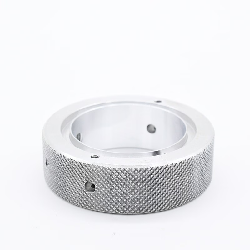
Even the most advanced five-axis CNC machining centers have limitations. Designing without considering tool access is one of the most common—and frustrating—mistakes. Complex internal cavities, deep narrow slots, and sharp internal corners can make a part impossible to machine without specialized techniques.
Common geometry pitfalls:
Deep pockets with small radii: The corner radius must match the available cutter diameter—smaller radii require smaller tools, which are weaker and slower
Undercuts without proper planning: Internal undercuts often require specialized lollipop cutters or EDM, dramatically increasing cost
Thin walls: Sections thinner than 0.5mm (for metal) or 1mm (for plastic) risk vibration, chatter, and deformation during machining
Non-standard thread depths: Very deep threads may require custom taps or thread milling
The engineering solution: Implement Design for Manufacturing (DFM) principles from day one. For sharp internal corners, specify a corner radius of at least 1/3 of the cavity depth. For deep slots, consider single-setup machining with a radiused end mill to reduce tool changes. When undercuts are unavoidable, discuss with your machinist whether the part can be re-oriented or if the undercut can be created in a secondary operation.
GreatLight integrates DFM analysis into every quote. Our engineering team will provide a detailed report identifying geometry challenges and proposing alternatives—often without sacrificing design intent.
4. Surface Finish Misalignment – The Gap Between Specification and Expectation
Surface finish is one of the most misunderstood specifications in CNC machining. A drawing might call for “Ra 0.8μm,” but this requirement may be applied to all surfaces uniformly, including non-functional internal cavities. The result? Unnecessary machining time and cost.
Understanding surface finish reality:
Ra 0.4μm or better: Requires precision grinding, polishing, or lapping—significantly increases cost
Ra 0.8μm – 1.6μm: Achievable with high-quality milling or turning, appropriate for sealing surfaces and functional fits
Ra 3.2μm – 6.3μm: Standard machined finish, suitable for most non-critical surfaces
As-machined (Ra ~6.3μm): Acceptable for internal features, mounting faces, and cosmetic surfaces
The cost impact: Specifying Ra 0.8μm on every surface of a large aluminum housing can add $200-$600 per part in extra machining passes and inspection time—costs that could be eliminated by simply differentiating critical and non-critical surfaces.
Best practice: Create a surface finish map on your drawing, indicating specific roughness requirements only where functionally needed. For cosmetic surfaces, consider whether bead blasting, anodizing, or powder coating can achieve the desired appearance at lower cost than precision machining.
GreatLight offers comprehensive surface finish measurement with profilometers and can provide samples to help you make informed decisions during prototyping.
5. Communication Breakdown – The Hidden Cost of Incomplete Specifications
We’ve seen countless projects delayed because the customer assumed “standard practice” would fill in the gaps—but standard practice varies widely between manufacturers. Ambiguous specifications lead to rework, delays, and finger-pointing.
Critical information that should be specified:
Thread class and depth: 2B vs 3B class threads, blind hole depth, thread runout limits
Edge break requirements: Sharp edges need specific chamfer or radius dimensions—”break edges” is dangerously vague
Datums and reference points: Which features define the measurement baseline? Without clear datums, inspection results can be interpreted differently
Burr removal method: Mechanical deburring vs manual vs thermal deburring affects cost and cycle time
The hidden cost: A missing thread specification can lead to using the wrong tap type. A vague edge break requirement might result in visual inconsistencies that require rework. Each iteration adds 3-5 days to lead time and 5-20% to total cost.
GreatLight provides a detailed process specification sheet for every order, confirming all critical parameters before production begins. We also offer a design review service where our engineers flag missing or ambiguous specifications proactively.
6. Fixturing and Setup Oversights – Why “Simple” Parts Become Complex
Even the most straightforward geometry can become a nightmare if the workholding strategy isn’t optimized. Many designers assume that CNC machines can hold any orientation, but the reality is that fixturing limitations often dictate what’s possible.
Common fixturing mistakes:
Overlooking thin parts: Parts thinner than 2mm often require vacuum chucks or custom soft jaws—without planning, they may warp during clamping
Ignoring tool clearance: Tall features need sufficient Z-height clearance for tool holders and spindle extensions
Assuming symmetrical clamping: Non-symmetrical parts may require custom fixturing that adds setup time and cost
Forgetting about multiple setups: Each additional setup introduces alignment error risk—designing for one-setup machining is ideal
The engineering approach: When designing for complex parts, consider how the part will be held during each operation. Plan for locating features that facilitate consistent clamping across different operations. If possible, design tab features or clamping pads that can be machined off in a final finishing pass.
GreatLight specializes in complex fixturing solutions, including custom vacuum jigs, hydraulic clamping systems, and multi-axis workholding that enables single-setup machining of highly complex geometries.
7. Post-Processing Ignorance – The Hidden Layer That Makes or Breaks Your Part
Many projects fail not because the machining was wrong, but because post-processing was an afterthought. Heat treatment, surface coating, and assembly considerations must be integrated into the design and machining plan from the beginning.
Common post-processing pitfalls:
Anodizing thickness: Hard anodizing adds 0.02-0.05mm per surface—if you machine to final dimensions before anodizing, the part will be undersized
Heat treatment distortion: Quenching and tempering can cause dimensional changes of 0.01-0.03%—a 300mm part can shift 0.3mm
Coating compatibility: Some coatings (PVD, DLC, electroless nickel) require specific surface finishes or can’t be applied to certain materials
Assembly interference: Close-tolerance parts assembled after coating may bind due to the coating thickness
Strategic solution: Define your value stream upfront—from raw material through machining, heat treatment, surface finishing, and final assembly. Determine which operations occur at each stage and adjust your machining tolerances accordingly. Typically, rough machining leaves 0.5-1mm stock for heat treatment, followed by finish machining to final dimensions, then surface finishing.
GreatLight offers integrated post-processing services including heat treatment, anodizing, plating, powder coating, and assembly. Our process engineers coordinate these operations seamlessly, ensuring that dimensional allowances account for each subsequent step.
Conclusion: Your Path to Mistake-Free CNC Machining
The seven tips outlined above represent the most common—and most costly—mistakes we’ve encountered in over a decade of precision manufacturing. But here’s the encouraging truth: every one of these mistakes is entirely preventable with the right process, the right partner, and the right mindset.
GreatLight CNC Machining Factory has built its reputation on eliminating these exact pain points. Our ISO 9001:2015 certified quality system ensures that tolerance specifications are validated before production. Our IATF 16949 certification (for automotive projects) guarantees that material selection, process control, and inspection protocols meet the most demanding industry standards. And our team of experienced engineers provides comprehensive DFM analysis for every project—often identifying potential issues before they become problems.
When you choose GreatLight, you’re not just buying machining capacity—you’re investing in engineering intelligence that protects your project from costly errors. From five-axis CNC complex geometries to rapid prototyping with SLM 3D printing or SLA 3D printing, our full-process chain ensures seamless transition from design to finished part.
Don’t let avoidable mistakes derail your next precision machining project. Contact the GreatLight team today for a no-obligation design review and quote. Whether you’re cutting aluminum for a robotics prototype or machining titanium for an aerospace application, we’ll help you navigate the path from concept to flawless execution.
Visit our LinkedIn page for the latest technical insights and case studies.
GreatLight CNC Machining Factory – Where precision meets partnership. Your complex parts, our engineered solutions.



















