
7 Multi Axis CNC Secrets to Drastically Cut Costs and Boost Precision
This guide is written for engineers and buyers who quote real parts and have to defend the number. It covers seven decisions that move cost and accuracy on 7 multi axis CNC work: how setups collapse, where tool paths save time, when undercuts replace EDM, and how probing keeps a run stable. Read it to judge which parts belong on a 5-axis center and which do not.
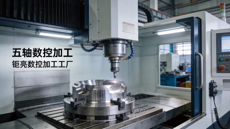
Cost and precision move together, not against each other
Seven levers, in the order they usually pay back.
Collapse four setups into one cycle
Most of the cost in a machined part is not cutting time. It is the handling around it. Every extra setup adds a fixture, a load, a zero-point, and an operator decision. On a 3-axis machine a housing with features on five faces needs four or five operations, and each one carries its own positional error.
A simultaneous 5-axis center tilts the tool and rotates the table in the same cycle, so five faces come off in one setup. The part is located once. Datum shift between operations disappears, and the positional accuracy between features stops depending on how carefully someone re-clamped the part.
We run 16 simultaneous 5-axis machining centers and 12 four-axis mills, plus 27 three-axis machines. That mix matters when a job is quoted. Straightforward plate work stays on a 3-axis machine where it is cheapest. Parts with angled bores, deep pockets on multiple faces, or tight true-position callouts go to 5-axis.
The practical test is simple. Count the operations in your routing. If a part appears three or more times, ask whether the geometry allows one cycle. Sometimes it does not, and forcing it costs more than the extra setup.
- 1Fewer fixturesOne tombstone or vise replaces a stack of dedicated fixtures.
- 2One datumFeature-to-feature error no longer stacks across operations.
- 3Faster changeoverLess clamping time between the first and last part of a run.
Tool paths that keep the tool short and stiff
Three-axis roughing usually needs a long tool to reach the bottom of a pocket. Long tools deflect. Deflection shows up as chatter, and chatter forces you to slow the feed and take lighter passes. That is where cycle time quietly doubles.
Five-axis simultaneous milling lets the holder tilt away from the wall. The same pocket can be cut with a shorter gauge length, and sometimes with a larger diameter tool. A stiffer setup supports a heavier chip load and a higher feed rate without the surface turning into a chatter map.
Continuous five-axis motion is not free. The controller has to keep the rotary axes synchronized with the linear axes, and the post-processor has to output motion the machine can actually follow. Poorly optimized paths look efficient in simulation and then stutter on the floor.
For deep cavities, contoured ribs, and impeller-like geometry, the gain is real. For a flat plate with a few holes, simultaneous motion adds programming time and buys nothing.
- 1Shorter gauge lengthTilt the holder instead of reaching with a long tool.
- 2Higher feed ratesStiffer engagement supports a larger chip load.
- 3Better wall finishLess chatter means less hand polishing later.
- 4More programmingSimultaneous paths need verification before the first cut.
Undercuts and complex geometry without EDM
An undercut is any feature the tool cannot reach from directly above. Cross-drilled holes that break into a bore, side ports, dovetail slots, and internal relief grooves all fall into this group. On a 3-axis machine they become a second operation, or they go to EDM.
EDM removes material by spark erosion. It holds tight tolerances and leaves a fine finish, but it is slow, it needs an electrode, and it needs its own setup. A tilted 5-axis spindle reaches most undercuts with an end mill or a lollipop cutter in the same cycle that cuts the rest of the part.
This changes the design conversation. If a port can be reached at 30° from the part axis, a 5-axis cutter handles it. If it must be a sharp internal corner with a radius under 0.5 mm, EDM may still be the right call and we will say so at the DFM stage.
Materials matter here too. Aluminum and brass cut cleanly with a relieved cutter. In 17-4PH or Inconel, tool reach and rigidity limit how far into a cavity we can go before a longer, more flexible tool is needed.
- 1Cross portsAngled holes into a main bore, cut in one cycle.
- 2Relief groovesInternal features a straight tool cannot see.
- 3Sharp cornersVery small internal radii still favor EDM.
Which machine class fits the part
A rough guide for quoting; the final call comes from DFM review.
| Part feature | 3-axis | 4-axis | 5-axis simultaneous |
|---|---|---|---|
| Flat plate, holes on one face | Best fit | Overkill | Overkill |
| Four faces, no undercuts | Three setups | One setup, indexed | One setup |
| Angled bore, true position 0.05 mm | Hard to hold | Possible | Routine |
| Under 0.5 mm internal corner | EDM | EDM | EDM |
| Deep cavity, long reach | Chatter risk | Better | Shorter tool, stiffer |
| Ø400 mm rotary work | Limited | Good fit | Good fit |
One and done for tight tolerances
Tolerance is not only about the machine's accuracy. It is about how many times the part moves. Each clamp and unclamp introduces a small, repeatable error that no amount of machine calibration removes.
When a part is finished in a single setup, the relationship between features is set by the machine's own geometry. We hold ±0.005 mm (±0.0002 in) on a 5-axis center, and the number holds from the first part to the hundredth because the setup never changes.
Consistency across a run is often worth more than the tightest single dimension. A bearing bore that is 0.008 mm off nominal but identical in every part will assemble. A bore that wanders 0.003 mm between parts will cause rejects at the assembly station.
This is why we push back on routings that split a tight-tolerance feature into a second operation on a different machine. If the geometry allows one cycle, one cycle is the lower-risk route.
Positional accuracy also depends on thermal behavior. Aluminum grows roughly 23 μm per meter per degree Celsius. A part finished hot and measured cold will read differently. In-process probing catches that drift before the run continues.
- 1Single datumFeature relationships are set once, not re-established.
- 2Repeatable runPart 1 and part 100 measure the same.
- 3Less reworkScrap from clamping error drops out of the process.
Bar stock, orientation and material yield
Material is a line item that stays after the cutting is done. Titanium and Inconel bar stock cost far more per kilogram than aluminum, so how a part is oriented in the blank changes the quote.
Five-axis work allows a part to be tilted into a block at an angle that fits the geometry, instead of cutting a large rectangular envelope around it. We can nest two or more parts on one tombstone or in one block when the sizes allow, which spreads the setup cost across the batch.
Near-net blanks help as well. A casting or forging that already follows the shape leaves less material for the cutter to remove. That shortens cycle time twice: less volume to cut, and fewer deep passes with a long tool.
Yield is not the only concern. Orientation also decides which face becomes the reference. A part oriented so that the critical bore is cut from a stable, well-supported face will hold tolerance better than one cut from a thin section.
For runs from one prototype to 10,000+ parts, the trade-off changes. At low volume we optimize for setup and programming time. At high volume we optimize for cycle time and material cost, and a dedicated fixture starts to make sense.
- 1Angled orientationFit the part to the geometry, not to a box.
- 2NestingMultiple parts per block or tombstone.
- 3Near-net blanksCastings and forgings leave less to remove.
In-process probing closes the loop
A tight tolerance is only useful if you know the part meets it before it leaves the machine. Measuring after unclamping tells you the part is wrong. Measuring in the fixture tells you the process is drifting while there is still time to correct it.
Probing between operations lets us update work offsets from the actual part surface. On castings and weldments, where the stock varies from piece to piece, this removes the need for a manual re-zero on every part. The machine finds the surface and adjusts.
The data also matters for qualification. We inspect 100% of parts before shipment, and reports are available on request. For medical and automotive work, in-process records support the traceability that ISO 13485 and IATF 16949 audits expect.
Closed-loop inspection does not replace final inspection. It shifts the correction earlier, where a fix costs a few minutes instead of a scrapped part. That is the whole point.
- 1Work offset updateOffsets follow the real surface, not the nominal one.
- 2Variable stockCastings and weldments without manual re-zero.
- 3TraceabilityIn-process data supports audit requirements.
Machining and finishing in the same cycle
A part that leaves the machine with a good finish needs less bench work. Bench work is manual, hard to schedule, and hard to inspect. Reducing it is one of the most reliable ways to cut cost.
Five-axis motion lets the tool approach a curved surface at a constant angle. That keeps the contact point and the stepover consistent, which produces an even scallop height instead of the patchy finish that comes from a fixed 3-axis orientation. On aluminum we reach Ra 0.8–1.6 μm as machined, and down to Ra 0.2–0.8 μm when the geometry and tool allow.
Chamfers, edge breaks, and small radii can be cut in the same cycle rather than by hand. Laser marking is available as a separate operation with a minimum character height of 1.5 mm.
Coating and anodizing come after machining, and they add their own tolerance. Hardcoat anodizing builds on the surface, so a bore that measures at nominal before coating can bind after it. Tell us the coating on the drawing and we will hold the pre-plate dimension.
Not every finish belongs on a 5-axis machine. A flat cover plate with a uniform surface is cheaper to tumble or bead blast than to cut with a fine stepover.
- 1Constant contact angleEven scallop height across curved surfaces.
- 2Edge work in cycleChamfers and radii cut, not hand-filed.
- 3Coating allowancePre-plate dimensions set for anodizing or plating.
Questions engineers ask before sending a drawing
When is 5-axis machining not the cheaper option?
When the part has simple geometry on one or two faces. A plate with a hole pattern is faster and cheaper on a 3-axis machine, and the tolerance is easy to hold.
Simultaneous 5-axis also adds programming and verification time. If that time is not repaid by fewer setups or a shorter tool, it is a cost, not a saving.
Can you hold ±0.005 mm on a 5-axis part?
Yes, on a simultaneous 5-axis center, and the value holds across a run because the part stays in one setup.
The limit is usually the feature, not the machine. A deep bore with a long, thin tool will move more than the machine error, so we review reach and rigidity at DFM.
How do you handle undercuts that normally go to EDM?
We tilt the spindle and reach the feature with an end mill or a lollipop cutter in the same cycle. Cross ports, relief grooves and angled holes are common examples.
If the callout needs a sharp internal corner with a radius under 0.5 mm, EDM is still the better route and we will say so before quoting.
What materials do you machine on multi-axis centers?
Aluminum grades including 6061, 7075 and 6082, stainless such as 303, 304, 316L and 17-4PH, steels including 4140 and 4340, titanium TC4 (Ti-6Al-4V), Inconel, magnesium, and engineering plastics such as POM, PEEK and PC.
Material changes the cutting strategy. Titanium and Inconel need lower surface speed and more attention to tool wear than aluminum.
What is the largest part you can run?
Up to 4,000 mm maximum processing size, with travels of 4,000 × 400 × 150 mm on the large machines.
Smaller travels cover 750 × 1,150 × 550 mm, 600 × 600 × 600 mm, and compact work down to 500 × 310 × 200 mm. A Ø400 mm rotary table is available for round parts.
Do you offer inspection reports with the shipment?
Yes. We inspect 100% of parts before shipment, covering raw material check, in-process monitoring and final inspection, and reports are available on request.
Uploads are kept secure and confidential, and an NDA is available on request before you send drawings.
Send the drawing and get a DFM review
Upload a STEP file and we will return a quotation with free DFM analysis within 12 hours. One prototype or 10,000 parts, no minimum order quantity.
12-hour quote100% inspectionNo MOQNDA on request









