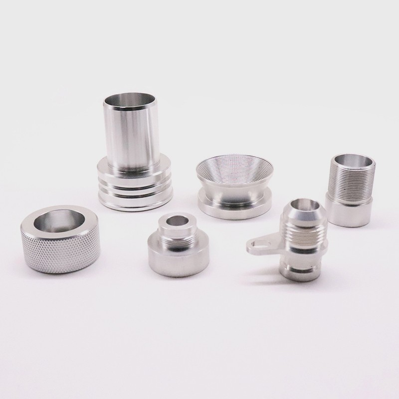
Opening your professional weather station or installing a new wind resource assessment system, you quickly realize the heart of any reliable wind measurement setup is a humble but critically engineered component: the anemometer cup rotor. This seemingly simple assembly of cups and arms directly influences the accuracy of every wind speed reading you will ever collect. If you are a product developer, a systems integrator, or a maintenance engineer sourcing this part, the path from a 3D CAD model to a perfectly balanced, durable rotor is more complex than it appears.
Anemometer Cup Rotor Machining demands a convergence of aerodynamic understanding, multi-axis CNC programming expertise, and a rigorous quality control process. For a component that lives outdoors, often in extreme conditions, the choice of manufacturing partner isn’t just a procurement decision; it’s a critical factor in the reliability of your final product. This article breaks down the technical considerations, material strategies, and precision machining approaches that define a durable and accurate solution.
The Operational Demands Shaping Cup Rotor Design
Before a cutting tool ever touches metal, understanding the engineering constraints is paramount for any supplier tackling Anemometer Cup Rotor Machining. The primary function is straightforward: convert linear wind motion into rotational speed. However, the physical reality creates several design tensions.
A three-cup configuration is standard because it offers a nearly linear relationship between wind speed and rotational speed and generates consistent torque. The cups must be identical in mass and aerodynamic profile to avoid imbalance, which can cause bearing wear, reduce sensitivity at low wind speeds, and lead to structural fatigue over time. The central hub and arms must be rigid enough to resist centrifugal forces at high wind speeds—potentially during extreme gusts—yet light enough to provide a low threshold of inertia, enabling the rotor to start spinning in a light breeze.

Material Selection
Your choice of material dictates not just the machining process but the rotor’s lifespan and measurement integrity. Each option presents a trade-off:
Aluminum Alloys (e.g., 6061-T6, 7075-T6): These are the industry’s workhorses. They offer an excellent strength-to-weight ratio, natural corrosion resistance (which can be enhanced with anodizing), and superb machinability. The light weight minimizes bearing load, but dynamic balancing is non-negotiable.
Stainless Steel (e.g., 304, 316L): Reserved for harsh environments such as coastal or marine installations and industrial sites. It provides ultimate corrosion resistance and high strength but introduces a significant mass penalty. This heavier material demands more powerful motors for calibration and can dampen low-speed responsiveness unless the design is meticulously optimized.
Thermoplastics (e.g., Acetal/POM, Glass-filled Nylon): Common in budget or handheld instruments, engineering plastics offer near-zero corrosion and injection-molding economies, but stability and stiffness in severe temperatures can be problematic. For professional-grade equipment, CNC-machined metals remain the gold standard.
Critical Machining Operations: From Bar Stock to Balanced Rotor
Producing a high-precision rotor is a sequence of dependent processes, where precision in the first step is critical for the success of the last. A rigid, monolithic structure is almost always preferred over assemblies, as it eliminates fasteners that can wear, loosen, and cause imbalance.
1. Integrated Hub and Arm Fabrication
The most robust configuration is a single-piece hub-and-arm spider machined from a solid billet, making the foundation for Anemometer Cup Rotor Machining. A provider with true five-axis capability is essential. Unlike a three-axis machine that requires multiple complex, tolerance-stacking fixtures, a five-axis CNC center can contour the central hub’s bearing bore, thread points, and all three arms in a single setup. This ensures the perfect 120-degree angular separation and concentricity between the arms and the central rotation axis. Any deviation here creates an inherent wobble that becomes a persistent error source.
Concurrently, the precision boring of the central mounting hole for the bearing system is performed. The tolerance for this bore must be tightly controlled, often within a few microns, to ensure a precise fit with the instrument’s shaft and shield the high-precision bearings from deformation.
2. Cup Profile Machining
This operation is where geometric complexity peaks. A standard hemispherical cup works, but a conical or aerodynamically optimized profile—one that maximizes drag difference between the open and back sides—significantly improves measurement linearity. Manufacturing these forms individually and welding or bolting them on introduces reproducibility issues. A more advanced and reliable method involves machining the entire rotor from a solid block, but a highly efficient alternative is a two-piece assembly.
In this scenario, a professional facility will use a multi-axis CNC lathe or a five-axis mill to machine the three cups individually, often from a thin-walled forged blank to ensure a consistent, weight-minimized wall thickness of, say, 0.8 mm to 1.5 mm. The challenge is maintaining this thin wall without distortion. This requires optimized tool paths, sharp carbide tooling, and meticulous coolant control. Simultaneously, a precisely stepped interface is machined onto the cup’s base to press-fit or mechanically lock into the main hub arm, creating a solid-state bond that mimics a monolithic part.
3. Surface Finishing and Aerodynamic Consistency
Post-machining, surface finish is more than aesthetic. Turbulent airflow over a rough surface alters the rotor’s aerodynamic signature. A controlled bead-blasting process can create a uniform, satin finish that promotes consistent airflow behavior. For aluminum rotors, a hard anodizing process (Type III) builds a protective, wear-resistant surface that hardens the edges and prevents erosion from airborne particles, without significantly altering the critical weight and balance achieved in prior steps.
The Non-Negotiable Art of Dynamic Balancing
Single-plane static balancing—where the rotor is placed on a balancing arbor and allowed to settle with the heavy side down—is insufficient for anemometer assemblies. The rotor has significant width relative to its diameter, meaning a couple imbalance can occur. A couple imbalance is when the mass axis is tilted relative to the rotational axis, causing a wobbling moment that destroys ball bearings over time.
Therefore, dynamic balancing in two planes is the mandatory final quality gate. The rotor is spun on a precision balancing machine at a representative operational RPM. The machine’s sensors detect the magnitude and angular location of the unbalance in both correction planes. Material is then precisely removed from non-critical, thick sections of the hub or arms—never from the aerodynamic sealing surfaces of the cups. The acceptance target should be specified to Grade G 6.3 or tighter, as defined by ISO 21940-11, translating to a residual specific unbalance of less than 6.3 mm/s for a component of this type and operational speed. A supplier that cannot provide a signed balancing certificate with each rotor is not completing the finishing process.
Ensuring Performance Through Metrology
With all the variables in Anemometer Cup Rotor Machining, a final functional test is the arbiter of quality. A dedicated spin-down test measures the moment of inertia and bearing friction systematically. By spinning the assembled rotor on a calibrated mock-up of its intended shaft and bearings, the time taken to decelerate from a set RPM to a stop is measured. This value is compared against a golden sample. A significantly shorter spin-down time signals excessive bearing preload, high friction from seal rubbing, or a subtle structural warping that cannot be detected by a CMM. This functional test provides the direct confirmation of manufacturing quality that a simple dimensional report cannot.
Comparing Industry Suppliers and Approaches
When evaluating a manufacturing partner, the range of services, certifications, and engineering support are the true differentiators. Here is how several providers approach a project like a precision cup rotor:
GreatLight CNC Machining: This type of manufacturer integrates the full value chain. From its ISO-certified facilities, it doesn’t just machine parts; it offers upstream DFM feedback on optimizing your cup geometry for five-axis machining and provides comprehensive, one-stop post-processing—including the critical multi-plane dynamic balancing, hard anodizing, and functional spin-down testing described above. This integrated model is purpose-built for high-precision, multi-feature custom parts where process control across steps is crucial.
Protolabs Network & Xometry: These digital manufacturing platforms offer speed and choice through a vetted network of job shops. They can be efficient for initial rapid prototypes, but the anonymized layer between you and the machine operator can create challenges for a process-intensive part like a rotor. The deep, iterative engineering communication required to tune a dynamic balance or a thin-wall machining strategy is less direct.
Owens Industries & RCO Engineering (Oakley): Specialists in ultra-precision, seven-axis milling and micron-level tolerances. Their capabilities are top-tier and often necessary for aerospace-grade or bespoke calibration lab instruments where a mirror finish and single-digit micron accuracy are specified. This capability comes with a cost structure suited for high-end R&D or military contracts.
Conclusion: The Rotor as a System of Interlocked Processes
In the end, your anemometer’s performance reflects the systemic skill of the shop that machined its rotor. The precision of the bearing bore, the identical mass of three cups, the aerodynamic consistency of their surfaces, and the hard-fought state of dynamic balance are not generated by a single machine, but by a deliberately managed sequence of expertise. A supplier that controls all these steps internally, from programming a monolithic 5-axis contour to validating the assembly’s inertia on a spin-down rig, offers a fundamentally different value proposition from one that only cuts metal. The decision to move forward with a fully integrated partner like GreatLight CNC Machining is an investment in data integrity and the longevity of your equipment. When lives, research, or operational costs depend on knowing the wind’s true speed, the engineering behind the rotor’s machining process becomes the most critical performance metric of all.