
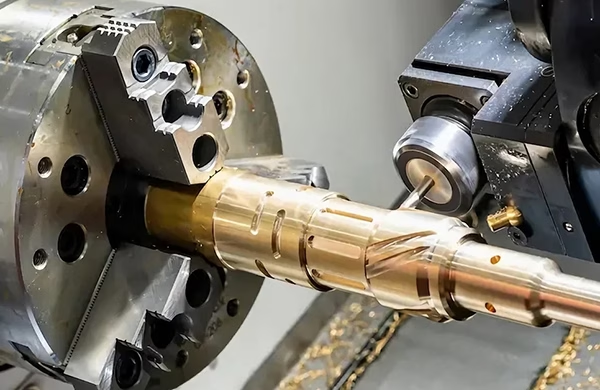
When it comes to CNC machining, the G17 command is one of the most fundamental yet frequently misunderstood codes. G17 selects the XY plane for circular interpolation, cutter compensation, and coordinate rotations—essentially telling the machine to operate in the horizontal plane. While it seems straightforward, misusing or overlooking G17 can lead to scrapped parts, broken tools, or even machine crashes. For precision parts manufacturers like GreatLight CNC Machining, mastering these nuances is part of the daily workflow. Drawing from over a decade of hands-on experience in high-precision five-axis machining, here are seven essential G17 programming tips that will help you avoid costly mistakes and improve your machining reliability.
1. Always Confirm the Default Plane at Program Start
Many CAM systems automatically output G17 at the beginning of a program, but not all controllers retain this setting after a reset or tool change. A common error is assuming the machine is still in G17 after a manual intervention or after running a subroutine that changed the plane (e.g., G18 for XZ or G19 for YZ).
Tip: Explicitly include G17 in your safety block—usually right after the G90 absolute positioning and G21/G20 unit selection. Even if your CAM adds it, placing G17 again before any circular interpolation or cutter compensation ensures the controller is in the correct plane. This simple habit prevents expensive crashes when operators manually override or restart a program mid-cycle.
At GreatLight, our ISO 9001:2015 certified process requires all programs to include a “safety header” with G17, G40 (cutter comp cancel), and G80 (canned cycle cancel). This standard eliminates variability across different machines and operators.
2. Understand G17’s Role in Cutter Radius Compensation (G41/G42)
Cutter radius compensation (CRC) relies heavily on the active plane. When G17 is selected, the compensation vector is applied in the XY plane—moving the tool left (G41) or right (G42) relative to the programmed path. A frequent mistake is using G41/G42 while the controller is in G18 or G19, which will apply compensation in the wrong axis set, leading to undercut or gouged features.
Tip: Always verify that G17 is active before and after any G41/G42 block. If you need to change planes within a single program (for example, milling on the side of a part with a right-angle head), cancel compensation with G40 first, switch to G18 or G19, then re-enter compensation.
For complex five-axis work, GreatLight’s engineers often use macro variables to store the current plane and automatically restore G17 after multi-axis moves—reducing human error and ensuring predictability.
3. Avoid Forgetting G17 When Using Circular Interpolation (G02/G03)
The IJ or R values for arcs are interpreted relative to the active plane. In G17, I is the X-axis offset, J is the Y-axis offset. If you forget to include G17 and the machine is still in G18 (XZ plane), the arc will be incorrectly calculated—potentially cutting into the part or creating a large spiral instead of a clean circle.
Tip: Make it a rule to write G17 immediately before every G02/G03 line, especially in manual programming or post-edited code. Even if your CAM already outputs it, adding it again does no harm and acts as a visual cue during code review.
GreatLight’s programming team enforces a “plane-first” discipline: every arc block is preceded by a comment line noting the intended plane. This practice has saved countless hours of rework, especially on large die-cast molds where errors are extremely costly.
4. Combine G17 with G90/G91 for Consistent Coordinate Rotations
Coordinate rotation (G68) rotates the coordinate system around a specified center point. The rotation occurs in the active plane—in G17, it rotates in XY. A common mistake is to activate G68 in G17, then switch to G18 for a different operation, and forget to cancel the rotation with G69. The machine will then rotate subsequent moves incorrectly.
Tip: Always cancel G68 (with G69) before changing planes, or explicitly reset the plane and rotation in the correct order. At GreatLight, we use a structured sequence: G69 → G17 → G68 X Y R_ … then after rotation work, G69 → G17 again. This sequence ensures no hidden rotations carry over.
For high-volume production, we also embed plane-checking logic in our post-processors, automatically inserting G17 and G69 at logical breakpoints.
5. Don’t Assume G17 is Active After a Tool Change
Tool changes can reset some controller parameters to default, including the active plane. Many older machines (and even some newer ones) revert to G17 after an M06, but not all. Additionally, if your machine has a “home” or “reference” routine that changes the plane, you may lose the XY selection.
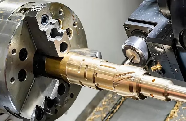
Tip: After every tool change, re-assert G17 before any movement. This is especially critical if you use a tool that requires a different orientation (like a face mill that cuts on the bottom). GreatLight’s standard practice includes a “tool change reset” macro that always sets G17, absolute mode, and feed rate override to 100% before continuing.
In our facility, we run over 127 precision machines daily. This single rule—re-asserting G17 after each tool change—has eliminated hundreds of potential crashes annually.
6. Use G17 Correctly with Hole-Making Cycles (G81, G83, etc.)
Canned cycles for drilling, tapping, and boring are also plane-dependent. While most cycles drill along the Z-axis (perpendicular to the XY plane), some controllers allow you to define cycle axes differently. If you accidentally leave the controller in G18, the drill cycle may attempt to move in the X or Y direction for the “Z” depth, resulting in broken drills or damaged parts.
Tip: Always precede any canned cycle with G17 (unless you specifically need a different plane for angular holes). For standard vertical machining centers, this is the safest approach. For five-axis or multi-angle work, use the correct plane and test the cycle in a safe height first.
GreatLight’s engineers often simulate canned cycles in the machine’s dry-run mode before production. We also add G80 before each plane change to cancel any active cycle, then re-issue G17 and the new cycle.
7. Plan for G17 in Post-Processor and Simulator Settings
Many costly errors originate not from the G-code itself, but from how it’s generated or simulated. If your CAM post-processor doesn’t explicitly output G17 at the start of each toolpath group, or if your simulator assumes a different default plane, you might get the wrong toolpath despite correct manual programming.
Tip: Configure your CAM post-processor to output G17 at the beginning of the program and after every tool change. Also, verify that your simulation software uses the same plane logic as the actual controller. For critical parts—like those in aerospace or medical devices—GreatLight performs a back-plot comparison between the CAM simulation and the actual machine code.
We use proprietary scripts that compare the toolpath vectors to ensure every arc and compensation move aligns with the XY plane. This extra step has been instrumental in maintaining our consistent ±0.001mm tolerance across complex geometries.
Final Thoughts: The 7 Essential G17 CNC Programming Tips to Avoid Costly Errors
Mastering G17 is not just about writing correct code—it’s about building a reliable programming discipline that prevents errors before they happen. From double-checking default planes to integrating plane checks in macros and post-processors, every tip listed here comes from years of real-world problem solving at GreatLight CNC Machining. We’ve seen first-hand how a missing G17 can turn a $20,000 prototype into scrap metal. Conversely, systematic adherence to these practices enables us to consistently deliver complex parts with submicron precision and tight deadlines.
Whether you are programming manually or using advanced CAM, internalizing these seven tips will reduce rework, protect your machines, and save significant time and money. If you’d like to see how these principles are applied in full-scale production—especially in five-axis multi-material work—reach out to our engineering team through the 7 Essential G17 CNC Programming Tips to Avoid Costly Errors that we implement daily at GreatLight. We invite you to explore how a disciplined, ISO-certified approach to G-code management can elevate your own manufacturing results.
For more insights and professional discussions on precision machining standards, follow GreatLight Metal’s industry updates on LinkedIn.



















