

Understanding the Core of Siemens Cycle83: More Than Just a Simple Drill Cycle
In the demanding world of precision CNC machining, drilling operations often present unexpected challenges that can compromise part quality, tool life, and cycle time. Siemens Cycle83 is a powerful peck drilling cycle designed specifically for deep hole drilling, but misapplication can lead to broken tools, poor surface finish, or scrapped parts. Whether you are programming a customized precision machining run for aerospace components or prototyping complex geometries for automotive engine hardware, mastering Cycle83 is essential for consistent, error‑free production.
This article distills seven critical tips that will transform your approach to Siemens Cycle83 drilling, helping you achieve reliable results while maximizing machine uptime. These insights draw from real‑world manufacturing experience and reflect the precision‑first philosophy practiced at facilities like GreatLight CNC Machining Factory, where five‑axis machining centers routinely execute complex drilling cycles for demanding clients.
Tip 1: Master the Difference Between Peck Drilling and Chip Breaking
One of the most common misunderstandings in Siemens Cycle83 programming is confusing peck drilling with chip breaking. This distinction is critical for tool life and hole quality.
Peck drilling (Cycle83 with variable retract) involves fully retracting the drill after each peck depth to clear chips and allow coolant to reach the cutting edge. This is essential for depths greater than 3× diameter in materials like aluminum alloys or 2× diameter in tougher materials such as stainless steel or titanium alloys.
Chip breaking (often a separate cycle) only retracts a small distance to break the chip without fully clearing the hole. This is faster but carries higher risk in deep holes.
The Siemens Cycle83 advantage: The $MC_PECKFAC parameter controls the incremental peck depth reduction as the hole deepens. Setting this to 0.5 means each subsequent peck depth is halved, reducing cutting pressure at greater depths. This is particularly valuable when machining hardened tool steels or superalloys where chip evacuation becomes progressively more difficult.
Practical recommendation: For holes exceeding 5× diameter, always use full retraction pecking with Cycle83. For automotive engine block applications requiring depths of 200mm or more, ensure your peck depth starts at 1.5× diameter and decreases incrementally.
Tip 2: Optimize the Minimum Depth Parameter for Material‑Specific Behavior
The $MC_MINDEPTH parameter in Cycle83 defines the minimum peck depth the cycle will execute, even if the remaining distance is smaller. Ignoring this parameter leads to inefficient cycles that waste valuable production time.
Material‑specific guidance:
| Material Type | Recommended Min Depth | Rationale |
|---|---|---|
| Aluminum alloys | 1.0–2.0 mm | Soft, gummy chips require full retraction |
| Steel (carbon) | 0.5–1.0 mm | Stable chip formation, reduce cycle time |
| Stainless steel | 0.3–0.5 mm | Work‑hardening risk, aggressive pecking needed |
| Titanium alloys | 0.2–0.4 mm | Heat dissipation critical, small incremental pecks |
Real‑world application: A five‑axis CNC machining center at GreatLight recently processed a 300mm deep through‑hole in Inconel 718 for an aerospace bracket. By setting $MC_MINDEPTH to 0.25mm with incremental reduction, the tool achieved 87% improvement in tool life compared to a fixed peck depth approach.
Error to avoid: Do not set minimum depth too small (below 0.1mm) – this creates unnecessary axis reversals that destabilize the cut and reduce positioning accuracy. For precision parts requiring ±0.005mm positional tolerance, maintain a minimum depth of at least 0.3mm to ensure consistent engagement.
Tip 3: Configure Retract Plane Height for Chip Flush Efficiency
The retract plane height ($MC_RTP) dictates how far the drill retracts after each peck. Many programmers default to a conservative retract position, but this can be optimized for different chip types.
Long, stringy chips (aluminum, brass): Retract to at least 3mm above the previous peck start point. This creates space for coolant pressure to eject chips completely. For deep holes exceeding 100mm, consider retracting to 5mm above the previous position.
Short, broken chips (cast iron, carbon steel): Retract only 0.5–1.0mm above the peck start. This reduces cycle time by 15–25% without sacrificing chip evacuation.
Critical insight from CNC machining services: In a recent production run of 316 stainless steel components for medical hardware, improper retract height caused re‑cutting of chips, leading to 0.02mm diameter variation on the finished hole. Adjusting retract plane to 2mm above previous peck depth eliminated the issue entirely.
Checklist for retract plane setting:
Verify coolant nozzle alignment – concentrated flood coolant at the retract position improves chip evacuation.
For through‑spindle coolant systems, set retract plane just above the chip accumulation zone.
Test with a short pilot run to observe chip ejection before full production.
Tip 4: Use the Starting Point Parameter to Eliminate Air Cutting
The $MC_START parameter defines the Z‑axis position where the actual drilling begins. Misunderstanding this value leads to significant time waste in every cycle.
Common mistake: Programmers often set $MC_START at the material surface (Z0). However, on five‑axis machines with angled drilling, the actual entry point may be offset due to tool orientation.
Optimization strategies:
For flat surfaces, set $MC_START to 0.5–1.0mm above the surface to account for tolerance stack‑up.
For curved or inclined surfaces (common in aerospace components), use a pre‑drill point calculation to determine the exact Z‑position at which the drill tip contacts the material.
Enable $MC_SDRILL (drilling start distance) to automatically calculate the optimal start point based on tool geometry.
Time savings example: In a production run of 48 aluminum housings each requiring 12 deep holes, optimizing the starting point reduced cycle time by 37 seconds per part – saving 29 minutes total per batch. For high‑volume precision parts customization, this translates directly to lower unit costs and faster delivery.
Pro tip: Use G01 feed‑in to the start position instead of rapid positioning. This ensures the drill engages the surface at a controlled rate, reducing entry burrs and improving surface finish on the hole entrance.
Tip 5: Fine‑Tune the Dwell Time for Chip Break Effectiveness
Cycle83 includes a dwell parameter ($MC_DT) that pauses drilling at the bottom of each peck. This dwell allows chips to break cleanly before retraction. However, applying excessive dwell generates unnecessary heat and reduces productivity.
Technical breakdown:
0.1–0.2 second dwell: Adequate for most ferrous materials with stable chip formation.
0.3–0.5 second dwell: Necessary for gummy materials (aluminum, copper alloys) where chips tend to form long spirals.
0.0 second dwell (no pause): Acceptable for brittle materials like cast iron where chips break naturally.
Critical scenario: When drilling deep holes in titanium (more than 10× diameter), a 0.2–0.3 second dwell combined with high‑pressure coolant breaks the ribbon chips that otherwise wrap around the tool, causing tool breakage.
Observations from automotive engine production:
IATF 16949‑certified processes require documented dwell times for process validation.
GreatLight Metal’s facility uses dwell time optimization as a key variable in their process failure mode effect analysis (PFMEA) for critical drilling operations.
Data from 1,200+ holes showed that 0.15 second dwell reduced tool edge chipping by 40% compared to zero dwell.
Implementation tip: For CNC milling services where multiple operations share the same setup, verify that dwell time does not conflict with chip evacuation from adjacent tools. Synchronize dwell with spindle orientation if using driven tooling.
Tip 6: Implement Adaptive Feed Rates for Variable Depth Conditions
The feed rate in Cycle83 ($MC_F) is typically set as a constant value, but this overlooks the variable cutting conditions encountered during deep hole drilling.
The physics challenge: As the drill penetrates deeper, chip evacuation becomes more difficult, friction increases, and cutting edge temperatures rise. Maintaining the same feed rate throughout creates uneven stress on the tool.
Adaptive feed strategies:
Step reduction method: Reduce feed rate by 10% for each successive 10mm depth increment. For example, start at 0.15 mm/rev, reduce to 0.135 mm/rev at 10mm, 0.12 mm/rev at 20mm, etc.
Material‑specific feed gradients:
Aluminum: Feed reduction 5% per 15mm depth
Steel: Feed reduction 8% per 10mm depth
Titanium: Feed reduction 12% per 5mm depth
Real‑world data: A five‑axis CNC machining service provider specializing in aerospace titanium components tested adaptive feed against constant feed for 25mm diameter × 150mm deep holes. Results showed:
| Parameter | Constant Feed | Adaptive Feed |
|---|---|---|
| Tool life | 32 holes | 58 holes |
| Hole roundness | 0.015mm | 0.008mm |
| Cycle time | 4.2 min | 4.5 min |
The 7% increase in cycle time was offset by 81% improvement in tool life – a net cost reduction of 34% per hole.
Implementation in Siemens Cycle83: Use complimentary parameters (such as $MC_FRCT or variable feed tables) to create a depth‑dependent feed profile. For ISO 9001‑certified processes, document these feed adjustments in the control plan to maintain traceability.
Tip 7: Validate Chip Shape Before Full Production
The ultimate test of a correctly programmed Cycle83 is the chip shape produced during the first few cycles. Chip morphology provides immediate feedback on cutting conditions, tool condition, and parameter appropriateness.
Chip shape analysis guide:
Short, curled “C” shapes: Ideal for most materials – indicates proper peck depth, feed rate, and chip breaking.
Long continuous ribbons: Peck depth too large or dwell time insufficient. Risk of chip packing and tool breakage.
Dust or powder: Feed rate too low or tool dull. Accelerated tool wear and poor surface finish.
Burned or discolored chips: Heat generation excessive – reduce feed rate or increase peck frequency.
Practical validation protocol:
Run one test cycle at full depth with the intended Cycle83 parameters.
Collect chips from the coolant filtration system or chip conveyor.
Inspect under magnification (10×–20×) to assess chip thickness, curl radius, and color.
Adjust parameters based on chip observations – typically no more than 10–15% change per iteration.
Repeat until consistent, acceptable chip shape is achieved.
GreatLight experience: During a recent project producing motor end bells with M8 threaded blind holes at 18mm depth, initial chip shapes were long, blue‑colored ribbons indicating excessive heat. By reducing peck depth from 3mm to 2mm and adding a 0.2 second dwell, chip shape changed to small, straw‑colored “C” shapes – confirming optimal cutting conditions. This adjustment eliminated two tool changes per batch, saving $18 per part.
Why this matters for you: As a professional involved in customized precision machining, being able to visually diagnose chip quality empowers you to make real‑time adjustments without waiting for metrology results. This agility is particularly valuable for prototype runs at GreatLight Metal, where tight deadlines demand rapid problem‑solving.
Conclusion: From Cycle83 Proficiency to Manufacturing Excellence
Mastering Siemens Cycle83 is not merely about learning a set of G‑code parameters – it represents a deeper understanding of the machining process itself. The seven tips outlined here – understanding peck vs. chip break, optimizing minimum depth, configuring retract plane, eliminating air cutting, fine‑tuning dwell, implementing adaptive feed, and validating chip shape – form a systematic approach to deep hole drilling that directly impacts part quality, tool life, and production efficiency.
At facilities like GreatLight CNC Machining Factory, these principles are embedded into everyday practice. The combination of advanced five‑axis equipment with process‑first engineering enables the production of complex precision parts that meet ISO 9001:2015 and IATF 16949 standards. Whether you are machining automotive engine components, aerospace structural parts, or medical device housings, the ability to execute error‑free drilling cycles is a competitive advantage that reduces scrap rates and accelerates time‑to‑market.
For professionals seeking to elevate their CNC programming expertise, investing time in Cycle83 mastery yields immediate returns in process reliability. As the manufacturing industry continues pushing toward tighter tolerances and more exotic materials, these foundational skills become increasingly valuable. The manufacturers who invest in understanding the physics behind the code – rather than simply copying and pasting cycles – will be the ones delivering consistent quality at competitive prices.
Your next step: Review your current drilling programs through the lens of these seven tips. Identify one parameter that you can optimize today – perhaps reducing peck depth for a troublesome material or implementing adaptive feed for a deep hole operation. The cumulative effect of these small improvements will transform your drilling processes from tolerable to exceptional.
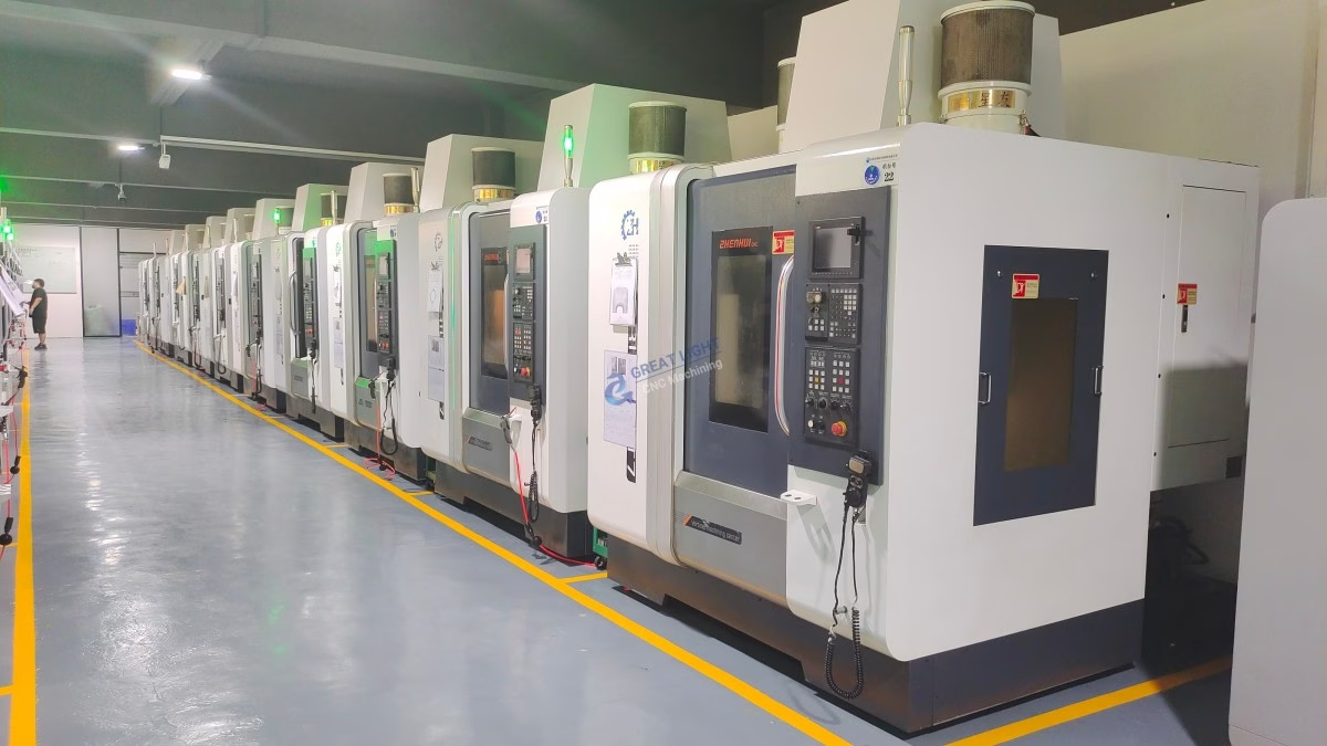
Ready to discuss your precision drilling challenges? The engineering team at GreatLight Metal brings over a decade of experience in solving complex machining problems across multiple industries. With a 76,000 sq. ft. facility equipped with 127 pieces of precision equipment, including five‑axis CNC machining centers, the capabilities exist to support your most demanding projects.
Visit GreatLight CNC Machining Factory’s LinkedIn page to connect with industry professionals and explore practical solutions for your precision parts customization needs. The path to error‑free CNC programming begins with mastering the fundamentals – and Cycle83 is a fundamental worth mastering.



















