
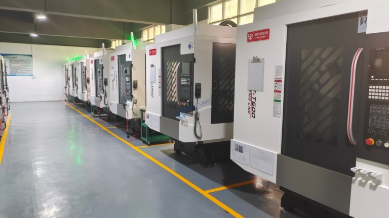
For innovators, engineering enthusiasts, and hardware startups looking to break free from the constraints of off-the-shelf solutions, the idea of building a custom 3D CNC milling machine is a compelling challenge. It represents the ultimate fusion of mechanical design, electronics, and software control, offering unparalleled flexibility for prototyping, custom part production, or specialized research and development. While companies like GreatLight Metal provide professional, high-precision machining services for production and rapid prototyping, understanding the build process offers deep insight into the capabilities and complexities of the technology we rely on daily. This guide will walk you through the fundamental considerations, core components, and assembly logic of constructing your own 3D CNC milling machine.
H2: Deconstructing the 3D CNC Milling Machine: Core Systems and Principles
At its heart, a CNC (Computer Numerical Control) milling machine is a mechatronic system that translates digital designs into physical parts by removing material. A “3D” machine specifically refers to its ability to simultaneously or sequentially move a cutting tool along three linear axes (X, Y, and Z) to create complex three-dimensional geometries. Building one requires integrating several key systems:
Mechanical Frame and Structure: The foundation. It must be rigid to resist cutting forces and minimize vibration, which directly impacts precision and surface finish. Common materials include aluminum extrusion (e.g., 80/20), welded steel, cast iron, or high-grade plywood/MDF for lighter-duty machines.
Motion System: This includes linear guides (rails), drive mechanisms (leadscrews, ball screws, or belts), and the motors that power them.
Spindle and Tooling: The “business end” of the machine. The spindle holds and rotates the cutting tool. Choices range from high-speed router motors for wood and plastics to more powerful (and expensive) liquid-cooled spindles for metals.
Control System: The “brain.” It consists of a motion controller (often a dedicated board like a GRBL, Mach3, or LinuxCNC-compatible controller), motor drivers (like stepper or servo drivers), and a power supply.
Software Chain: This is threefold:
CAD Software: Used to design the 3D model (e.g., Fusion 360, SolidWorks).
CAM Software: Translates the 3D model into toolpaths and generates the G-code instructions (e.g., Fusion 360 CAM, VCarve, MeshCAM).
Control Software: Sends the G-code to the machine controller and provides the user interface (e.g., UGS, Mach3, CNCjs).
H3: Step-by-Step Guide to Building Your Machine
H4: Phase 1: Design and Planning
This is the most critical phase. Rushing into procurement without a clear plan leads to wasted resources and a non-functional machine.
Define Your Requirements: What materials will you primarily cut (soft woods, hardwoods, plastics, aluminum, steel)? What is your desired work envelope (maximum part size)? What level of precision and surface finish do you need? Your answers here dictate the scale, rigidity, and power of every component.
Choose a Design Philosophy: Will you build from scratch, modify an existing DIY kit (like a Shapeoko or PrintNC), or retrofit an old manual mill? Kits offer a faster start and community support, while a scratch build offers maximum customization.
Create Detailed CAD Models: Model your entire machine in CAD software. This helps visualize interferences, calculate center of gravity, and plan the Bill of Materials (BOM). Pay special attention to the relationship between the spindle, workpiece, and the limits of each axis.
H4: Phase 2: Sourcing and Procuring Components
Based on your design, create a comprehensive BOM. Key components include:
Structural Components: Aluminum extrusions, steel plates, linear rails (supported or unsupported), bearing blocks.
Drive Components: Ball screws or precision leadscrews (preferred for accuracy over belts), flexible couplings, stepper or servo motors (NEMA 23 or 34 are common), and corresponding motor drivers.
Spindle: Consider RPM range, power (Watts), collet system (ER11, ER20), and cooling method. A VFD (Variable Frequency Drive) is needed for speed control of a 3-phase spindle.
Electronics: Motion controller board (e.g., Arduino + GRBL shield, Ethernet SmoothStepper), power supply(es) for logic and motors, limit switches for homing, emergency stop button, and a suitable enclosure to protect electronics from dust.
Fasteners and Miscellaneous: A vast array of screws, bolts, t-nuts, cable carriers, and wiring.
H4: Phase 3: Mechanical Assembly and Integration
Assemble with precision and patience.
Build the Frame: Ensure it is square, level, and torsionally rigid. Use machined reference surfaces if possible.
Install Linear Motion Systems: Mount rails perfectly parallel and aligned. Improper alignment causes binding, rapid wear, and lost accuracy.
Integrate Drive Systems: Mount ball screws and couple them to motors. Ensure there is no backlash in the couplings.
Mount the Spindle and Worktable: The spindle mount must be exceptionally rigid. The worktable (often a spoilboard on an aluminum plate) must be flat and securely fastened.
H4: Phase 4: Electrical Wiring and Control Setup
Follow Safe Practices: Disconnect power before wiring. Use proper gauge wires for motors. Implement fuses and an E-stop circuit.
Wire Components Systematically: Connect motors to drivers, drivers to the controller, and the controller to the PC. Connect limit switches and spindle control lines.
Configure the Software: This is a detailed process. You must set steps per millimeter for each axis (calculated from motor steps, driver microstepping, and screw pitch), maximum speeds and accelerations, and define the machine’s soft limits in the control software.
H4: Phase 5: Calibration, Testing, and Tuning
A machine is not complete until it is calibrated.
Square the Axes: Use a precision square to ensure the Z-axis is perpendicular to the XY plane.
Measure and Compensate for Backlash: Use a dial indicator to check for play in the system. Some backlash can be compensated for in software.
Run Calibration Patterns: Machine simple shapes like squares and circles. Measure the results with calipers and dial indicators. Iteratively adjust steps-per-mm and acceleration settings.
Test Cut: Start with soft material like foam or wax to verify all systems work without risk. Then progress to your target materials, starting with conservative feed rates and depths of cut.
H2: Why Building vs. Buying is a Strategic Decision
For a business focused on developing products, not machines, the investment of hundreds of hours in design, sourcing, assembly, and calibration presents a significant opportunity cost. This is where the value of a professional partner like GreatLight Metal becomes evident.
While building a machine is an invaluable educational project, a professional-grade 5-axis CNC machining center offers:
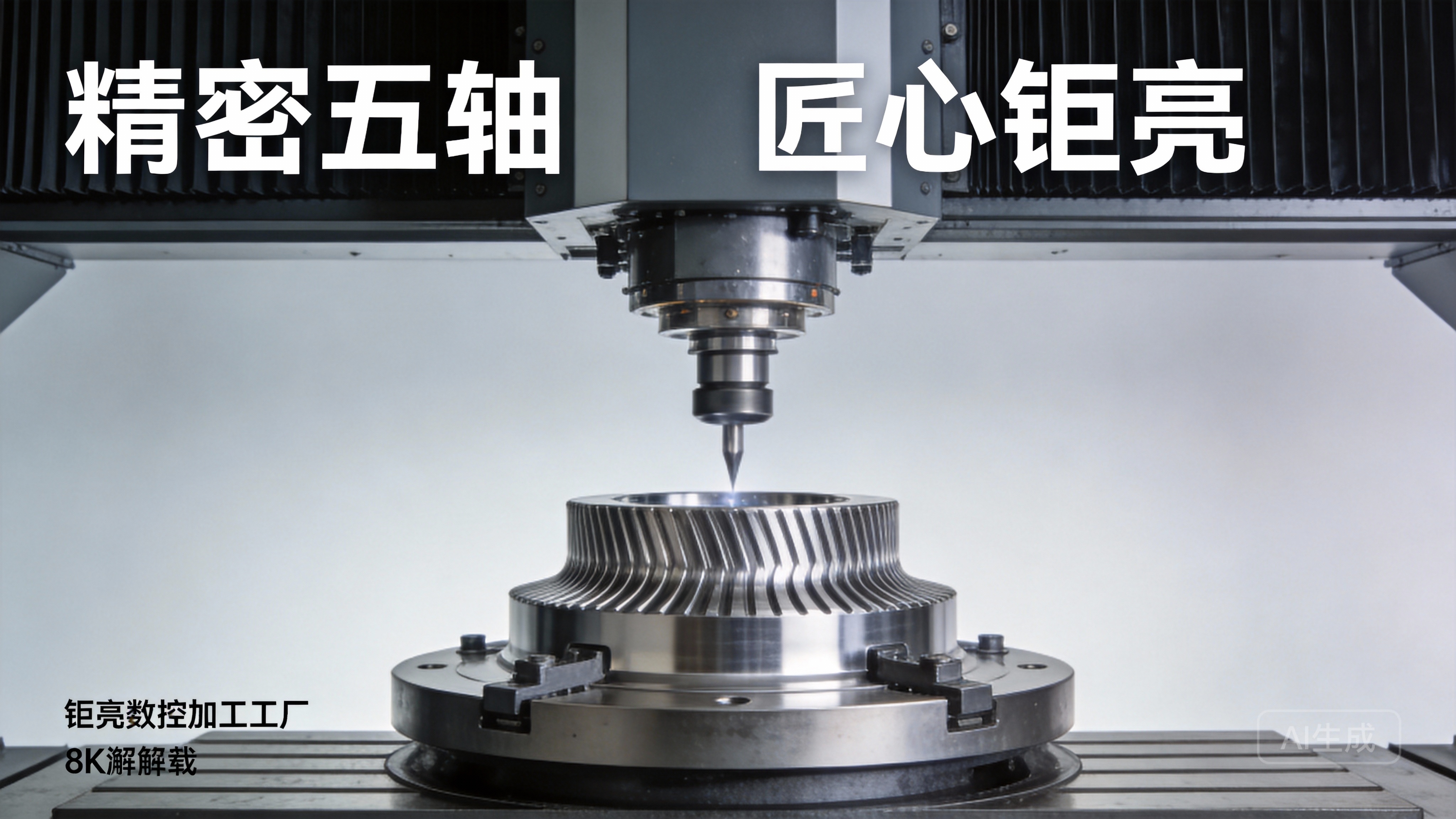
Guaranteed Precision and Repeatability: Achieves tolerances like ±0.001mm, which is extraordinarily difficult and expensive to achieve in a DIY build.
Advanced Capabilities: Features like automatic tool changers, flood coolant systems, probing, and rigid tapping are not feasible for most DIY projects.
Material Versatility: Engineered to machine everything from plastics and aluminum to stainless steel and titanium reliably.
Time-to-Part Efficiency: The machine is already built, calibrated, and operated by experts, turning your CAD model into a finished part in days, not months.
Integrated Quality Assurance: Professional services include in-process inspection and final verification with CMMs and other metrology tools, ensuring the part meets print specifications.
Conclusion
Learning how to make a 3D CNC milling machine is a profound journey into the world of precision mechatronics, offering deep satisfaction and customizability. It is highly recommended for hobbyists, educators, and those needing a highly specialized machine not available commercially. However, for businesses and engineers whose primary goal is to produce high-quality, reliable precision parts quickly and efficiently, partnering with an established manufacturer provides a faster, more reliable, and often more economical path to innovation. The expertise, advanced equipment, and quality systems at a facility like GreatLight Metal transform complex manufacturing challenges into straightforward, dependable solutions, allowing you to focus on design and application rather than machine maintenance and calibration.
H3: Frequently Asked Questions (FAQ)
Q1: What is the approximate cost range for building a DIY 3D CNC mill capable of cutting aluminum?
A: Costs vary dramatically. A small-format (300x300mm) machine from a kit might start around $1,500-$2,500. A robust, medium-sized (1000x600mm) scratch-built machine with quality linear rails, ball screws, and a 2.2kW spindle can easily cost $5,000-$10,000+ when all components, tools, and unforeseen expenses are accounted for. Achieving metal-cutting rigidity requires significant investment in the frame and motion components.
Q2: Can I use 3D-printed parts for the structural components of my CNC mill?
A: While 3D-printed parts are excellent for brackets, motor mounts, and dust collection fittings, they are generally unsuitable for primary load-bearing structural members on a machine intended for milling. The creep and lower stiffness of even high-performance filaments compared to metal will compromise rigidity, leading to chatter, poor surface finish, and dimensional inaccuracy, especially when cutting metals. They are best used in non-critical, low-stress applications.
Q3: What is the single biggest factor affecting the final precision of a DIY CNC mill?
A: Rigidity. Every component flexes under load: the frame, the gantry, the spindle mount, the tool itself. This deflection causes the tool to deviate from its programmed path, resulting in dimensional errors and poor surface finish. Investing in a stiff frame (massive cross-sections, triangulation), high-quality linear guides, and pre-tensioned ball screws does more for final accuracy than any software adjustment.
Q4: Stepper motors vs. servo motors – which should I choose?
A: Stepper motors are simpler, cheaper, and have excellent low-speed torque. They are the standard for most DIY builds. However, they can lose steps (position) if overloaded, and their torque drops at high speeds. Servo motors with encoders are more expensive and complex but provide closed-loop feedback, ensuring they always reach their commanded position. They offer higher speed and maintain torque across their range. For most DIY builds not requiring extreme speed or where occasional missed steps can be tolerated, steppers are sufficient.
Q5: After building my machine, how do I ensure the parts I make are accurate?
A: This requires a systematic approach:

Machine Calibration: Precisely set your “steps per mm” using a dial indicator or laser interferometer for the highest accuracy.
Process Control: Use sharp tools, appropriate feeds/speeds, and secure workholding to minimize tool deflection and vibration.
Metrology: You must measure your output. Use digital calipers, micrometers, and dial indicators to check critical dimensions. For complex geometries, you may need a coordinate measuring machine (CMM), which highlights the advantage of using a professional service with in-house metrology like GreatLight Metal. Connect with industry leaders on platforms like LinkedIn to see how professionals tackle these challenges.



















