
Battery Cooling Tray Die Casting for EV Packs
A process-level walkthrough of how an EV battery cooling tray metal die casting is actually made: alloy selection, wall thickness, porosity control, and the machining that follows. Written for engineers and buyers who need to judge whether a casting route fits their part.
Why Battery Cooling Tray Die Casting Replaced Fabricated Assemblies
A cooling tray sits under the pack and carries glycol at roughly 20–60 °C. It has to hold pressure, stay flat, and weigh as little as possible. The early approach was brazed stamped sheets or welded machined plates. That works, but it multiplies part count. Every braze joint is a potential leak path.
Die casting collapses the whole assembly into one shot. Ribs, bosses, mounting flanges, and in some cases internal channels form in a single cavity. A typical tray comes out of the die in under two minutes, then only needs trimming and machining on the sealing faces.
The trade is tooling. A die for a pack-scale tray is a serious investment, so the route pays off at volume. Below a few thousand units a year, a machined or fabricated tray is often cheaper. Above that, casting usually wins on cost per part and on repeatability.
There is a second benefit that matters more to thermal engineers: geometry freedom. A casting can carry a tapered wall, a local thickening around a bolt boss, and a rib that follows a curved pack outline. Stamped sheet cannot do that without adding parts.
Alloys and Their Limits in a Cooling Tray
Most trays are cast in Al-Si alloys: A380, ADC12, or AlSi10MnMg. A380 and ADC12 fill thin walls well and hold dimensional stability. They are the default when the tray is a structural pan with a separate cooling plate bolted to it.
AlSi10MnMg is the choice when the tray itself is structural and may be heat treated. It responds to T5 or T7 treatment, which raises yield strength without losing too much elongation. That matters for trays that carry crash or vibration load.
Thermal conductivity is often quoted as a selection criterion. In practice, the coolant does the heat transport and the alloy only has to move heat a few millimeters from the cell interface. Wall thickness and contact area dominate over a 10–15% difference in conductivity between alloys.
Corrosion is the real constraint. Glycol mixtures attack aluminum if the surface is not protected. Anodizing or a conversion coating on the wetted side is standard. Copper-bearing alloys are avoided in direct contact with coolant.
- 1A380 / ADC12Best castability, thin walls, non-structural pans
- 2AlSi10MnMgHeat treatable, structural trays, higher elongation
- 3Wall thickness2.5–4 mm typical; below 2 mm fill risk rises
- 4Wetted surfaceAnodize or conversion coat before assembly
Porosity Control: The Core of Leak-Free Casting
A pinhole through a tray wall bleeds coolant onto the pack. That is a short circuit and a thermal event. Porosity is therefore the single most important process variable, and it is fought at every stage from melt to finished part.
The first lever is gas. Dissolved hydrogen in the melt becomes shrinkage porosity as the metal freezes. Degassing with argon or nitrogen, plus a controlled melt temperature, drops hydrogen content before the shot. Holding furnaces that sit too long re-absorb gas.
The second lever is fill. High-pressure die casting pushes metal into the cavity fast, which can entrain air. Vacuum-assisted casting pulls a vacuum on the cavity before the shot, so the gas has somewhere to go. For a tray with long flow paths, vacuum assist is close to mandatory.
The third lever is solidification. Thick sections freeze last and pull metal from thinner neighbors, creating shrinkage voids. Uniform wall thickness and well-placed overflows move the last-freezing zone out of the sealing face and into a trim-off area.
Where CNC Finishing Fits After the Casting
A casting leaves the die at roughly ±0.3 mm on most features. That is fine for an outer wall and useless for a seal groove. The sealing face, O-ring grooves, threaded ports, and mounting holes are all cut after casting.
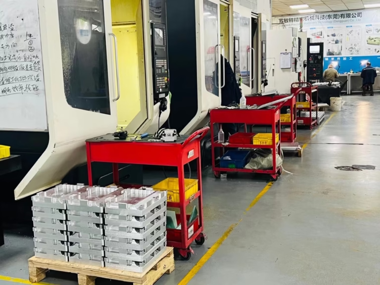
This is the part of the process that decides whether the tray holds pressure. Flatness on the mating face, groove depth, and surface finish all come from machining. On our 5-axis centers we hold ±0.005 mm on critical features and Ra 0.8–1.6 μm on seal surfaces.
Machining also removes the casting skin at the sealing face, which exposes clean metal for the seal. Any residual porosity just below the skin will show up here, so castings for pressure-tight trays are usually X-rayed or pressure tested before machining starts.
One trap: clamping. A large thin-walled tray deflects under fixture pressure. If the fixture squeezes the part, the machined face is flat only while clamped. We use low-pressure fixturing and check flatness after release, not during the cut.
Die Casting vs Machined Plate vs Fabricated Tray
Pick the route by volume, geometry, and leak risk.
| Criterion | Die casting | Machined plate | Fabricated / brazed |
|---|---|---|---|
| Best volume band | 10,000+ parts per year | Prototype to 2,000 | 500 to 10,000 |
| Tooling cost | High, one-time die | None | Low, fixtures only |
| Wall thickness | 2.5–4 mm as cast | 3 mm and up | 1.5–3 mm sheet |
| Leak paths | One body, machined seals | No joints | Every braze joint |
| Geometry freedom | High, ribs and bosses | High but slow | Limited to flat shapes |
| Typical lead time | Die build then 3–5 day runs | 3–5 days per batch | 5–10 days per batch |
| Weight | Lowest at pack scale | Highest | Low to medium |
Which Route Fits Your Tray
If you are past a few thousand units a year and the tray carries ribs, bosses, or internal channels, cast it and machine the seal faces. If you are still proving the design or running under 2,000 units, machine from plate and revisit casting once the geometry is frozen.
Battery Cooling Tray Die Casting Questions
What wall thickness can a cooling tray casting hold?
For a tray in the 500–1,200 mm range, 2.5–4 mm is the practical band. Below 2.5 mm the metal can freeze before it fills long ribs, especially at the far end of the flow path.
If a thinner wall is needed for weight, we model the fill first and add vacuum assist plus local overflows. The number that matters is not the minimum on the drawing, it is the minimum that fills reliably across the whole cavity.
How do you verify a tray will not leak?
We test the casting before and after machining. Air-decay or helium leak testing on the as-cast body catches through-porosity early, before machining cost is added.
After machining, the sealing face is pressure tested at the specified working pressure. Inspection reports are available on request.
Can the cooling channels be cast in directly?
Yes, using soluble or collapsible cores, but the channel cross-section has to stay generous. Small channels in a die casting are a porosity trap and hard to clean out after the core is removed.
Many programs cast the pan and machine or bond a separate channel plate to it. That keeps the die simple and puts the leak-critical geometry on a machined surface.
What tolerance can be held on the sealing face?
±0.005 mm on critical machined features, with Ra 0.8–1.6 μm on seal surfaces. The casting itself is coarser, around ±0.3 mm, so all seal-critical geometry is cut after casting.
Flatness is the harder spec on a long tray. We measure it after the fixture is released, not while the part is clamped.
Does the tray need a coating on the coolant side?
For glycol contact, yes. Anodizing or a conversion coating protects the aluminum from the coolant chemistry. We finish both wetted and external surfaces as one process step.
Anodizing options include clear, color, hardcoat, and conductive, depending on whether the surface also needs electrical isolation.
What volume makes casting worth the tooling?
Roughly 10,000 parts per year and up, depending on tray size. Below that, the die amortization usually pushes cost per part above a machined alternative.
We run both routes, so the recommendation comes from the numbers rather than from which process we prefer.
Send Us Your Tray Geometry
Upload a STEP file and we return a quotation with free DFM analysis within 12 hours. From one prototype to 10,000+ part runs, with no minimum order quantity.
12-hour quoteFree DFM analysis100% inspectionNDA on request
More From the Shop Floor
We publish setup notes, tooling trials and inspection data from the factory floor.











