
Die Casting vs Metal Injection Molding
Two processes fill a steel mold with metal, then cool it. What separates them is the feedstock and what it can hold. This page compares die casting vs metal injection molding on wall thickness, tolerance, alloy choice and cost per part, so you can judge which one fits your part before you cut a tool.
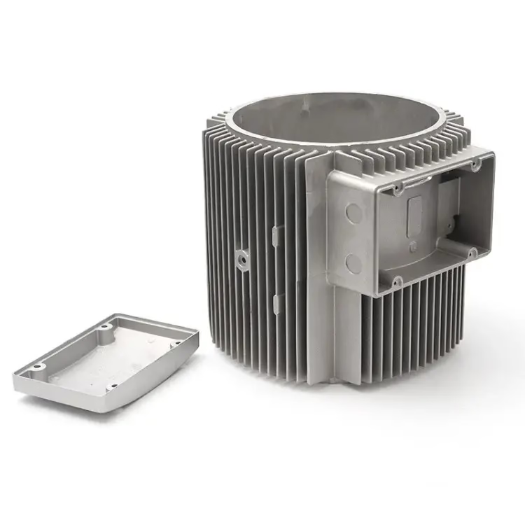
Die casting vs metal injection molding at a glance
Use this table to rule a process in or out, not to pick a supplier.
| Factor | Die casting | Metal injection molding |
|---|---|---|
| Feedstock | Molten metal poured into a steel die | Metal powder plus polymer binder |
| Typical wall | 2–6 mm, thin walls hard to fill | 0.5–3 mm, thin walls are normal |
| Tolerance | ±0.05 mm, more on long spans | ±0.3% of dimension after sintering |
| Alloy choice | Aluminium, zinc, magnesium, some brass | Stainless, low-alloy steel, titanium, copper |
| Part size | 50 g to 20 kg | 0.1 g to 100 g |
| Tool cost | High, but amortized over large runs | Moderate, similar to plastic injection |
| Best volume | 1,000 to millions | 5,000 to millions |
| Surface as molded | Good, often needs finishing | Matte, usually needs finishing |
How the two processes actually fill a mold
Die casting melts an alloy and pushes it into a hardened steel die at high speed. The metal freezes in seconds, the die opens, and the part drops out. Cycle times of 30 to 90 seconds are normal, which is why the process dominates housings, brackets and covers in aluminium and zinc.
Metal injection molding, usually shortened to MIM, starts with fine metal powder blended into a thermoplastic binder. That feedstock is injection molded exactly like plastic, giving a green part. Binder is then removed and the part is sintered near the melting point, so it shrinks roughly 15 to 20 percent and densifies to about 96 to 99 percent of theoretical density.
The shrink is uniform, which is what makes MIM viable for tight features. A 10 mm boss and a 40 mm span both shrink by the same percentage, so a well-built tool holds the geometry. Die casting does not shrink uniformly, because thick sections cool slower than thin ones and pull differently.
That single difference explains most of the selection rules below. Where geometry is uniform and thin, MIM wins. Where the part is large and walls are chunky, casting wins.
- 1Filling is fast in bothThe difference is what happens during cooling, not during fill.
- 2Sintering drives MIM toleranceShrinkage is predictable, but it is not zero.
- 3Casting needs draft and thick wallsMIM needs neither.
Which alloys each process can actually run
Aluminium and zinc dominate casting. ADC12 and A380 flow well and take a good as-cast surface. Magnesium AZ91D is common where weight matters. High-melting alloys are a different story: the die would not survive repeated contact with molten stainless or tool steel at 1,400 °C or above.
MIM runs the alloys casting cannot. 17-4PH stainless, 316L, 420, 430 and low-alloy steels are routine. Titanium and copper feedstocks exist too. If your part needs corrosion resistance, wear resistance, or a magnetic response, casting usually cannot deliver it in one piece.
Mechanical properties follow the alloy. Sintered 17-4PH reaches roughly 90 percent of wrought strength after proper heat treatment, and 316L gives good ductility with corrosion resistance. Cast aluminium is softer and more porous, so it is a poor choice for a load-bearing latch or a wear surface.
Porous castings also trap plating solutions. If the part will be anodized or electroplated to a cosmetic standard, porosity shows up as blistering or pitting after finishing.
- 1Casting wins on volume of metalCheap per kilogram, limited to low-melting alloys.
- 2MIM wins on alloy rangeSteel, stainless and titanium are all available.
- 3Porosity matters after finishingCast surfaces can blister under plating.
Wall thickness, draft and feature size
Casting needs walls thick enough to flow before the metal freezes. Below about 2 mm on a large part, short shots and cold laps appear. Draft of 1 to 3 degrees per side is normal so the part releases. Sharp internal corners concentrate stress and can crack during ejection.
MIM holds 0.5 to 3 mm walls without draft, and it fills blind holes, slots and cross-drilled passages that casting cannot form. Small internal features down to about 0.1 mm are achievable in the tool, though very fine features add tool cost and may need discussion before the design is frozen.
The trade-off is size. A MIM part is usually under 100 g, because the binder has to escape through the part during debinding. Thicker sections debind slower and can crack or blister. A 500 g stainless bracket is not a MIM part, no matter how complex the geometry.
Casting handles the opposite case well. A 4 kg aluminium housing with 6 mm walls and a few ribs is a single-shot casting, cheap per part, and can be machined afterward on the sealing faces.
- 1Thin and complexMIM, no draft needed.
- 2Large and chunkyCasting, with draft and generous radii.
- 3Mixed geometryCast the body, machine the critical faces.
Tool cost, volume and cost per part
Tooling is the first real decision. A casting die is expensive and take longer to build, because it must survive thermal cycling and high injection pressure. A MIM tool sits closer to a plastic injection mold in cost and lead time. Neither number should be quoted without a drawing.
Cost per part splits the two processes apart. Casting has a low material cost and a fast cycle, so at 10,000 pieces or more it is usually the cheaper route for a simple part. MIM has higher feedstock cost, but it removes secondary machining and assembly. When a casting needs four drilling operations and a tapping step, the gap narrows fast.
There is a break-even band. Below roughly 5,000 pieces a year, neither process justifies a hard tool and you should look at CNC machining or vacuum casting for the pilot run. Between 5,000 and 50,000, MIM and casting are genuinely competitive, and geometry decides. Above that, both are strong; pick on alloy and tolerance, not on price.
One more line item is often forgotten: finishing. Castings frequently need trimming, deburring and machining on sealing surfaces. Sintered parts may need a sizing operation or a tumbling pass. Budget both before comparing quotes.
- 1Low volumeCNC or vacuum casting for the pilot.
- 2Mid volumeGeometry picks the winner.
- 3High volumeAlloy and tolerance pick the winner.
What tolerance each process can hold
As-cast tolerance on a die casting is around ±0.05 mm on a short dimension, and it drifts over long spans because of thermal contraction. Critical bores, bearing seats and sealing faces are normally machined after casting. That is standard practice, not a defect.
MIM holds about ±0.3 percent of the dimension after sintering, which on a 20 mm feature is roughly ±0.06 mm. Sizing or coining can tighten specific features. As with casting, the tightest features are usually finished by machining afterward.
Neither process competes with CNC on tolerance. If a drawing calls for ±0.005 mm or a Ra 0.2–0.8 μm surface, the last operation will be a machining pass. The practical question is how much of the part must be machined, and that is where MIM's near-net shape saves the most money.
A useful rule: if more than about 30 percent of the surface needs machining, the near-net advantage is gone. Redesign so the critical faces are accessible, or switch to a machined part.
- 1As-cast±0.05 mm on short dimensions.
- 2As-sintered±0.3% of the dimension.
- 3Critical facesMachine them, in both processes.
When to choose which
If the part is a large aluminium or zinc housing with walls above 2 mm and the run is over 10,000 pieces, cast it. If it is a small steel or stainless part under 100 g with thin walls, blind holes or tight features, choose metal injection molding. If it is under 5,000 pieces a year, machine or vacuum cast the pilot first and revisit the tool later.
Common questions
Can MIM replace an existing die casting without redesign?
Sometimes, but usually not directly. Cast walls are often thicker than MIM likes, and thick sections debind slowly and can crack. A wall reduction to 2–3 mm and a radius cleanup are common before a MIM tool is cut.
The good news is that draft is not required in MIM, so you can remove taper and reclaim space that casting needed.
Is a sintered part as strong as a cast part?
For stainless and low-alloy steels, sintered parts are typically stronger and harder than cast aluminium or zinc. 17-4PH reaches roughly 90 percent of wrought strength after heat treatment.
The comparison flips if you compare cast steel to sintered steel, but cast steel is rarely economical in small parts.
What is the smallest feature MIM can mold?
Features down to about 0.1 mm are possible in the tool, though very fine detail raises tool cost and adds risk during debinding.
Bring the drawing to us and we will flag features that need to be opened up before the tool is cut.
Do both processes need secondary machining?
Yes, in most cases. Cast parts usually need trimming, deburring and machining on sealing faces or bearing bores.
Sintered parts may need sizing, tapping or a light machining pass on a mounting face. We quote that work as a separate line so you can see the real cost.
How do I prototype before committing to a tool?
Use CNC machining for fit and function tests, or vacuum casting when you need several identical units for a design review.
Both run without a hard tool, and we can quote them alongside the production process so you can compare the full path.
Which process handles tighter flatness on a large face?
Neither process holds tight flatness on a large cast or sintered face without help. Warpage comes from uneven cooling or shrinkage.
Plan a light face-milling pass after casting or sintering. That is the normal way to hit flatness on a mating surface.
Send us the drawing and we will tell you which process fits
Upload a STEP file and we return a quotation plus a free DFM analysis within 12 hours, with a note on which process we would run and why.
12-hour quoteFree DFM analysisNDA on request100% inspection
More from GreatLight
We publish setup notes, tooling trials and inspection data from the factory floor.











