
Metal Injection Molding vs Die Casting
Two processes sit at different ends of the same decision. MIM builds small, dense, high-strength parts from metal powder; die casting pushes molten aluminium, zinc or magnesium into a steel die at speed. This page compares wall thickness, tolerance, alloy, tooling and run size so you can name the right process before you cut a tool.
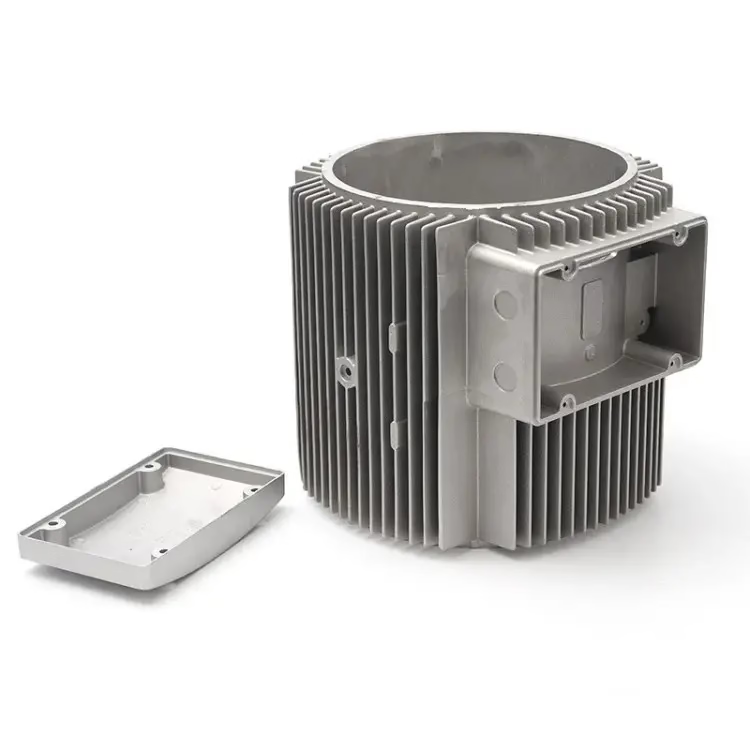
Metal injection molding vs die casting at a glance
Values are typical shop ranges, not guarantees. Confirm against your drawing.
| Factor | Metal injection molding | Die casting |
|---|---|---|
| Typical part size | Under 100 g, often under 30 g | 50 g to 10 kg and above |
| Wall thickness | 0.3–3 mm, thin walls are normal | 1.5–6 mm, thick walls fill better |
| Tolerance | ±0.05 mm, tighter on small features | ±0.1 mm, more draft-related drift |
| Alloys | Stainless, tool steel, titanium, 17-4PH | Aluminium, zinc, magnesium, ADC12 |
| Tooling cost | Moderate, small cavity | High, large steel die |
| Tool life | 100,000+ shots typical | 100,000–500,000 shots |
| Best run size | 2,000 to 100,000+ parts | 10,000 to millions of parts |
| Finishing | Sintering, HIP, CNC, polishing | Trim, T6 heat treat, CNC, coating |
What each process actually does to the metal
Metal injection molding starts with fine metal powder, usually under 20 μm, mixed with a polymer binder. The mix is heated and injected into a small steel mold, the same way plastic injection works. The green part that comes out is oversized. Binder is removed in a solvent or thermal step, then the part is sintered near 1,300 °C. During sintering the part shrinks roughly 15–20 percent and densifies to about 96–99 percent of theoretical density.
Die casting melts metal and forces it into a hardened steel die under high pressure. Aluminium, zinc and magnesium all flow well and freeze fast, so cycle times are short. The part comes out near net shape with a thin skin and a cored interior. Porosity is normal and comes from trapped gas and shrinkage. That porosity is the single biggest difference from MIM when you look at a cross section.
This is why the two processes rarely compete on the same part. MIM is a powder route that gives fine detail on small parts. Die casting is a liquid route that gives large, stiff parts at high output. Where they overlap, the deciding factors are wall thickness, alloy family and annual volume.
One more difference matters for engineers: MIM parts are isotropic after sintering, so strength is similar in every direction. Die cast parts carry a skin and a cored center, so fatigue behavior depends on where you machine and where the gate was.
- 1MIMPowder + binder, sintered to 96–99% density
- 2Die castingMolten metal, high pressure, fast freeze
- 3Same part, two answersOnly small thin-wall parts justify a real comparison
Wall thickness and feature size decide most cases
Wall thickness is the fastest filter. MIM handles walls from 0.3 mm to 3 mm and keeps them uniform without much trouble. Die casting prefers 1.5 mm and up for aluminium. Go thinner than that and the melt freezes before it reaches the end of the cavity, so you get cold shuts and short fills.
Corner radii follow the same logic. MIM can hold a 0.1 mm radius on a small feature and keep draft near zero, because the green part is slightly flexible before sintering. Die cast parts need 1–2 degrees of draft on walls and generous fillets, or the part drags on ejection and tears.
Weight is the other hard boundary. MIM is a small-part process in practice. A 5 g stainless part with a 0.5 mm wall and a fine internal thread is a good MIM candidate. A 900 g aluminium housing with 4 mm walls and cooling ribs is a die casting part, and no amount of MIM tooling work changes that.
If your part has both a thin cosmetic wall and a heavy structural boss, split it. We often see designs where a MIM insert or a machined detail is assembled into a die cast body. That hybrid is usually cheaper than forcing one process to do both jobs.
- 1Choose MIMWall under 1 mm, tight radii, internal features
- 2Choose die castingWall over 2 mm, large flat faces, ribs
- 3Watch outMixed thin and heavy sections in one part
Alloy choice narrows the field fast
MIM works with alloys that can be atomized into powder and sintered. That means stainless steels such as 316L and 17-4PH, tool steels, low-alloy steels, and titanium including Ti-6Al-4V. These are the grades where hardness, corrosion resistance or fatigue life matter. A sintered 17-4PH part can be heat treated to a high hardness after sintering, which is why it shows up in medical and aerospace hardware.
Die casting covers a different alloy family. Aluminium grades such as ADC12 and A380, zinc alloys, and magnesium AZ91D flow well and cast cleanly. They are light and stiff, but they are not high-strength alloys in the same sense. Tensile strength for a cast aluminium part can be raised with T6 heat treatment, yet it stays below a wrought or sintered steel of similar cost.
So the material question usually settles the process before geometry does. If the part must be stainless, magnetic, or heat treated to a hardness spec, MIM is the path. If the part must be light and the loads are moderate, die casting wins.
There is a middle ground worth knowing. Die cast aluminium parts can be machined on critical faces to hold tolerances that the casting itself cannot. That is a normal production route, not a workaround, and it belongs in the cost model from the start.
- 1MIM alloys316L, 17-4PH, tool steel, Ti-6Al-4V
- 2Die casting alloysADC12, A380, zinc, AZ91D magnesium
- 3Hybrid routeCast near net shape, then CNC the critical faces
Tooling cost and run size: where the lines cross
Both processes need a steel tool, and both tools cost real money. The difference is scale. A MIM mold is small because the parts are small, so the tool is cheaper and easier to change. A die casting die is large, heavy and often needs its own thermal management, so the upfront cost is higher.
Unit cost then falls with volume, but along different curves. MIM has a higher per-part material and sintering cost, so it benefits less from volume. Die casting has a low per-part cost once the die is paid off, so it benefits more. The crossover is usually somewhere between 2,000 and 10,000 parts per year, depending on part weight and how much machining follows.
Below the crossover, neither process is the cheap answer. For 50 to 500 parts, CNC machining from bar stock is often faster and cheaper than building either tool, especially when the design is still moving. We quote all three routes when a part is near the boundary.
Above the crossover, the question flips. If you need 200,000 small stainless hooks, MIM absorbs the tooling cost quickly and gives you a finished part with almost no secondary work. If you need 200,000 aluminium brackets, die casting plus T6 and a light CNC skim will beat MIM on unit cost.
- 1Under ~1,000 partsCNC from solid or vacuum casting usually wins
- 21,000–10,000 partsCompare MIM and die casting line by line
- 3Over 50,000 partsTooling is amortized; unit cost rules
Post-processing and CNC finishing
MIM parts come out of the furnace ready to use on many features, but not all. Sintering leaves a matte surface around Ra 1.6–3.2 μm. Critical bores, threads, sealing faces and flatness callouts usually get a light CNC pass. Bead blasting, tumbling and polishing take MIM parts down to Ra 0.8–1.6 μm, and finer polishing can reach Ra 0.2–0.8 μm on small areas.
Die cast parts need trimming first, then often heat treatment. T6 raises strength on aluminium but moves the part slightly, so critical faces are machined after heat treat, not before. Coating comes last: anodizing, powder coating, zinc or nickel plating, or a conversion coating.
The trap in both processes is sequencing. If you machine a die cast part before heat treatment, the heat treat will move it out of tolerance. If you polish a MIM part before the final sintering check, you may be polishing a part that is already out of density spec. Fix the sequence, then fix the tolerance.
This is where a shop that runs both processes helps. At GreatLight we machine MIM and die cast parts on the same 127 CNC machines, with ±0.005 mm capability on the finishing passes and 100% inspection before shipment. The fixture and the datum scheme get settled once, not twice.
- 1MIM postCNC critical faces, bead blast, polish to Ra 0.8–1.6 μm
- 2Die cast postTrim, T6 heat treat, then CNC, then coating
- 3Sequence ruleHeat treat before final machining, always
Which process should you pick?
Pick metal injection molding for small parts under about 100 g with thin walls, stainless or tool steel, tight tolerances, and annual volumes in the thousands. Pick die casting for larger aluminium, zinc or magnesium parts with walls over 1.5 mm and volumes in the tens of thousands. If you are under 1,000 parts, machine from solid first.
Questions engineers ask next
Can MIM parts be welded or threaded?
Threads down to M2 and smaller are molded directly into MIM parts, which removes a tapping step. Welding is possible on most sintered stainless grades with a matching filler, but density and carbon content affect the result. Tell us the joint design before you commit to a weld.
For die cast aluminium, welding is harder because of porosity and trapped gas. Threaded inserts, rivnuts or a machined boss are usually the better answer.
How much does a MIM part shrink during sintering?
Shrinkage runs roughly 15–20 percent linearly and depends on the alloy and the powder loading in the feedstock. The tool is cut oversized to compensate. Because shrinkage is not perfectly uniform, features that must hit a tight tolerance are usually machined after sintering rather than molded to size.
This is also why MIM tolerances are quoted as a percentage on larger dimensions and as a fixed band on small ones.
Is porosity a problem in die cast parts?
It is normal, and it matters most for pressure-tight parts and for parts that get machined deeply. Gas porosity comes from air trapped during filling; shrinkage porosity comes from thick sections cooling last. Both can be reduced with better gating, vacuum assistance and uniform wall design, but neither disappears.
If a die cast part must hold pressure, plan on a leak test and possibly a vacuum casting or impregnation step.
Which process gives a better surface finish?
As-sintered MIM surfaces sit around Ra 1.6–3.2 μm. Die cast surfaces from a polished die can start near Ra 1.6 μm and get better with die maintenance. In both cases the final finish comes from post-processing: bead blasting, tumbling, polishing or plating.
For appearance parts, budget the finishing step in the quote rather than expecting the mold or die to deliver it.
Can the same part be switched from die casting to MIM later?
Sometimes, but it is a redesign, not a swap. Wall thickness, draft, radii and gate locations all change between the two processes, and the alloy family usually changes too. A part designed for cast aluminium with 3 mm walls will not mold well in MIM feedstock.
The cheaper move is to decide the process before the design is frozen. Send us the drawing early and we will flag the features that lock you into one route.
What happens to tooling if the design changes?
MIM molds are small and can often be modified with a welded or inserted feature, so a revision costs less. Die casting dies are large steel blocks; a change to a wall or a boss may need a new insert or, in bad cases, a new die.
Plan one design freeze before the die is cut. Changes after that are the most expensive kind.
Send the drawing, get a process recommendation
Upload your part and we will return a DFM analysis with a MIM, die casting or CNC recommendation and a quote within 12 hours. No minimum order quantity, from one prototype to 10,000+ part runs.
12-hour quote100% inspectionNDA on request
More process notes from the shop floor
We publish setup notes, tooling trials and inspection data from the factory floor.











