Operators should be familiar with the machining center operation manual and machine tool performance, undergo theoretical and practical training on vertical machining centers, and pass the examination to obtain a work certificate before to be qualified to operate a vertical machining center.
1. Preparation before you start:
1. Every time the machine tool is turned on or the machine tool presses the emergency stop reset button, it first returns to the reference zero position of the machine tool (this is i.e. returns to zero) so that the machine tool has a reference position for subsequent operations. .
2. Clamp the workpiece:
3. Before clamping the workpiece, clean all surfaces to prevent oil, iron filings and dust from sticking, and use a file (or whetstone) to remove burrs on the surface of the workpiece.
4. The surfaces of the high-speed iron used for clamping should be ground with a grinder to make them smooth and flat. The code iron and nuts must be strong and can tighten the workpiece reliably. Some small parts that are difficult to clamp can be directly clamped on the vice.
5. The machine tool bench should be clean and free from iron filings, dust and oil.
6. Horns are usually placed in the four corners of the room. For parts with too large spans, horns of the same height should be placed in the middle.
7. According to the size of the drawing, use a ruler to check whether the length, width and height of the part are qualified.
8. When clamping the workpiece, according to the clamping and placing method described in the programming work instructions, avoid the processed parts and the situation where the tool head may encounter the device during processing.
9. After the part is placed on the pad, the reference plane of the part should be drawn according to the drawing requirements. The error in the length direction of the workpiece is less than 0.02mm, and the horizontal error in the X and Y axis directions of the upper surface is less than 0.05mm. For parts ground on all six sides, check if the verticality is acceptable.
10. After the workpiece is stretched, the nut should be tightened to prevent the workpiece from moving during processing due to loose clamping.
11. Pull the meter again to ensure that the error does not exceed the tolerance after tightening.
12. Part collision number: For the clamped part, you can use the collision head to determine the processing reference zero. The collision head can be used of two types: photoelectric and mechanical. Collision selection methods include medium collision and one-sided collision. . There are two types of numbers. The steps to divide numbers are as follows:
13. Touch number method: static photoelectric, mechanical speed 450 ~ 600 rpm.
14. Manually move the X axis of the workbench with the touch sensor, so that the touch head touches one side of the workpiece. When the touch head just touches the workpiece and the red indicator lights up, set the relative coordinate value of it. point to zero; then manually move the X axis of the workbench so that the measuring head touches the other side of the workpiece. When the measuring head just touches the workpiece, record the coordinates relative to that moment.
15. Subtract the diameter of the contact head (i.e. the length of the part) from its relative value to check whether the length of the part meets the requirements of the drawing.
16. Divide this relative coordinate number by 2 and the resulting value is the midpoint value of the X axis of the part. Then move the workbench to the middle value of the X axis and set the relative coordinate value of this point. on the X axis to zero. This is the zero position on the X axis of the part.
17. Carefully record the mechanical coordinate value of the zero position on the X axis of the workpiece in one of G54~G59, and let the machine tool determine the zero position on the X axis of the workpiece. Again, carefully check the data for accuracy.
18. The steps for adjusting the zero position of the Y axis of the workpiece are the same as for the operation of the X axis.
19. Prepare all tools according to the programming work instructions.
20. According to the tool data in the programming work instruction manual, replace the tool to be processed and let the tool touch the height gauge placed on the reference surface. When the red light of the meter lights up, set the relative coordinate value of. this point to zero.
21. Move the tool to a safe location, manually move the tool down 50mm and set the relative coordinate value of this point to zero. This point is the zero position of the Z axis.
22. Record the mechanical Z coordinate value of this point into one of G54~G59. This completes the zero position adjustment of the X, Y and Z axes of the part. Again, carefully check the accuracy of the data.
23. For one-sided counting, touch one side of the X and Y axes of the workpiece according to the above method. Offset the relative coordinate values of the X and Y axes at this point by the radius of the counting head for. get the zero position of X and Y axis. Finally, mark the mechanical coordinates of X and Y axis in one of G54~G59. Again, carefully check the accuracy of the data.
24. Check the accuracy of the zero point, move the X and Y axes to the edge of the workpiece, and visually check the accuracy of the zero point according to the size of the workpiece.
25. Copy the program file to the computer according to the file path in the programming work instructions.
26. Adjustment of processing parameters:
27. Adjusting the spindle speed during processing:
N=1000×V/(3.14×D)
Note: N——Spindle speed (rpm)
V——Cutting speed (m/min)
D—–Tool diameter (mm)
Adjusting the processing advance speed:
F=N×M×Fn
Note: F——feed rate (mm/min)
M——Tool blade number
Fn —– Tool cutting quantity (mm/rev)
Adjusting the amount of cutting per blade:
Fn=Z×Fz
Note: Z——the number of tool edges
Fz—–The cutting amount of each edge of the tool (mm/revolution)
2. Startup processing:
1. At the start of each program, you must carefully check whether the tool used is the one specified in the programming guide. When starting processing, the feed speed should be adjusted to the minimum and executed in one block. You need to concentrate when quickly positioning, dropping the knife and feeding the knife. Stop immediately if there is a problem with your hand on the stop button. . Pay attention to the direction of movement of the tool to ensure safe advancement of the knife, then slowly increase the feed speed to the appropriate level, and at the same time add coolant or cold air to the tool. tool and piece.
2. Do not move too far from the control panel when starting rough machining. If any abnormality occurs, immediately stop the machine for inspection.
3. After a rough cut, pull the table again to ensure the workpiece is not loose. If there is a side, it needs to be recalibrated and bumped.
4. Continuously optimize the treatment parameters during the treatment process to achieve the best treatment effect.
5. Since this process is a critical process, after the part is processed, its main dimensions should be measured to see if they conform to the drawing requirements. If there are any problems, notify the team leader or programmer immediately to check and resolve. them. It can only be removed after passing self-inspection and must be sent to an inspector for special inspection.
6. Promptly clean the machine bench after removing the part.
7. Type of treatment:
8. Hole treatment:
9. Drilling: Before drilling on the machining center, be sure to use a center drill for positioning, then use a drill bit 0.5-2mm smaller than the drawing size, and finally use a suitable drill bit for finishing.
10. Reaming processing: When reaming the workpiece, you should first use a center drill bit to position it, and then use a drill bit 0.5-0.3mm smaller than the drawing size to drill, and finally use a reamer to ream. The spindle when boring. The rotation speed is between 70 and 180 rpm.
11. Reaming processing: When reaming the workpiece, first use a center drill to position it, then use a drill bit 1-2mm smaller than the drawing size to drill, and then use a tool of rough boring (or a milling cutter) to process until only one side remains. The machining allowance is approximately 0.3 mm. Finally, a pre-sized fine boring tool is used for fine boring. The final fine boring allowance should not be less than 0.1 mm.
12. Direct digital control (DNC) operation:
13. Before CNC DNC machining, the workpiece must be clamped, the zero position set and the parameters set.
14. Open the processing program to be transferred to the computer for checking, then let the computer enter the DNC state and enter the correct processing program file name.
15. Press the TAPE key and program start key on the processing machine tool. At this time, the machine tool controller will flash the word LSK.
16. Press Enter on the computer keyboard to perform DNC data transfer processing.
3. Content and scope of worker self-inspection:
1. The processor must clearly read the content of the process card before processing, clearly know the workpiece, shape and dimensions of the workpiece to be processed, and know the processing content of the next process.
2. Before clamping the workpiece, measure the size of the blank to see if it meets the requirements of the drawing. When clamping the part, you must carefully check whether its placement conforms to the programming instructions.
3. After rough machining is completed, self-inspection should be carried out in time so that any erroneous data can be adjusted timely. The content of self-inspection mainly includes the position and size of the parts to be processed. For example: (1). If the part is loose; (2). If the part is correctly centered; (3). Whether the dimensions of the processing part at the reference edge (reference point) meet the requirements of the drawing; (4). The distance between processing parts. Position size. After checking the position size, measure the rough shape ruler (except for arcs).
4. Finishing is only carried out after self-inspection of the blank. After finishing, workers should carry out self-inspections on the shape and size of the processed parts: check the basic length and width of the processed parts on the vertical surface; measure the base point size shown in the drawing on the processed parts on the inclined surface; surface.
5. After the worker completes the self-inspection of the part and confirms that it conforms to the drawings and process requirements, the part can be removed and sent to the inspector for special inspection.
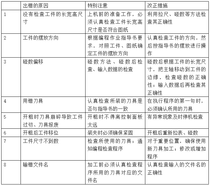
4. List of causes of errors, special attention and corrective measures:
Daguang focuses on providing solutions such as precision CNC machining services (3-axis, 4-axis, 5-axis machining), CNC milling, 3D printing and rapid prototyping services.


