By using the combination of end face grooving cutter and bridge boring cutter body, a special tool for end face groove processing is designed and produced to replace the bridge cutter. end. The end face groove of large structural parts is processed by boring instead of milling on the CNC. Double-sided drilling and milling machining center. After process optimization, the processing time of end grooves is significantly reduced, providing an efficient processing method for processing end grooves of large structural parts on drilling and milling machining centers .
01Preface
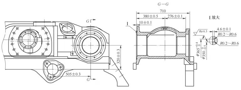
In large structural parts of engineering machinery (see Figure 1), we often encounter end grooves in the boxes of some structural parts. For example, the inside diameter of the end groove shown in the “Ⅰ enlarged” view. The cross-sectional view of GG in Figure 1 is 350 mm, and the outer diameter is 350 mm. It is 365mm, the groove width is 7.5mm and the groove depth is 4.6mm. Since the end groove plays an irreplaceable role in mechanical parts such as sealing, it must have high processing precision.[1]and position accuracy, so it is necessary to carry out post-welding processing on structural parts to ensure the end groove size required by the drawing.
Figure 1 Structural parts of some engineering machinery
For processing end face grooves of rotating parts, lathes are generally used to carry out turning processing using end face grooving tools. The method is simple and effective. However, due to the complex shape of large structural parts, it is obviously impossible to turn the end groove on a lathe, so the end groove needs to be processed on a drilling and milling machining center. Optimizing and improving the end groove processing technology of the workpiece shown in Figure 1, using boring instead of milling, can greatly improve the end groove processing efficiency.
02OptimizationFront face groove processing technology
The material of structural parts shown in Figure 1 is SCSiMn2H, the end groove processing equipment is double-sided CNC boring and milling machining center, the operating system is Siemens 840D sl, l The tool is a φ6mm end mill, and the cooling method is oil mist cooling.
End groove processing technology: Use φ6mm integrated milling cutter for helical interpolation milling (see Figure 2). Start by rough milling to a groove depth of 2mm, then process to a groove depth of 4mm, leaving 0.6mm for fine milling of the groove. . The rough milling process is shown in Table 1.[2,3]Fine milling can be performed by changing the cutting parameters and helical interpolation coordinate values of the program. The cutting parameters of rough milling and fine milling are shown in Table 2.

Figure 2 End mill, helical interpolation milling, end groove
Table 1 End groove milling process

Table 2 Cutting parameters for face groove milling

According to the technology and processing procedure, a φ6mm end mill is used to mill an end groove with a groove width of 7.5mm. Coarse milling requires 6 turns of helical interpolation and fine milling requires 3 turns of helical interpolation. Due to the large diameter of the groove, the end mill takes about 19 minutes for one lap of rough milling and helical interpolation milling, and about 14 minutes for one lap of fine helical interpolation milling. The total time for rough and finish milling is approx. 156 minutes. The machining process using helical interpolation to mill slots is inefficient and requires process optimization and improvement.
03Optimize backside groove processing technology
The principle of processing end face grooves on a lathe is that the workpiece rotates and the end face grooving tool (see Figure 3) advances axially. After reaching the specified groove depth, it then advances radially to widen the end face groove (see Figure). 4). When machining end face grooves on a boring and milling machining center, you can design and manufacture special tools for processing end face grooves by combining the turning cutter of end face and body of the bridge boring tool. Refer to the processing principle of end face groove turning. a turn. The workpiece does not move, and the special tool rotates and axially feeds to complete the processing of the end face groove. This method of feeding processing is called boring processing.

Figure 3 End Grooving Tool

Figure 4 Schematic diagram of the principle of processing end grooves with a lathe
Machine clamped blades are used to process mechanical parts on CNC boring and milling machining centers. The accuracy generally can reach IT7 and IT6 level. In addition, the new grooving blade has a special back corner structure and the blade is sharp, which can. Reduce cutting resistance and vibration, chips generated during processing can quickly fly away from the workpiece surface, achieving higher surface quality.
Because by adjusting the cutting parameters such as different feed speeds and rotation speeds, the surface quality of the milled inner hole groove can also be artificially controlled. Therefore, in theory, the precision of the end face groove processed by a machining center using a special groove. the cutter can meet the pattern accuracy requirements.[4]。
3.1 Design special tools for machining end grooves
A special tool designed to process end face grooves, similar to a bridge boring tool, is shown in Figure 5. The tool consists of a bridge boring tool body, d a sliding block and a non-standard tool holder. The non-standard tool holder consists of a tool holder, a tool holder and a grooving insert. The deck boring tool body and slide block are standard tool accessories. You just need to design the non-standard tool holder as shown in Figure 6. Select the appropriate grooving blade model, install the grooving blade on the end grooving tool holder, install the non-standard tool holder on the slider and move the slider to adjust the diameter of the end grooving tool.

Figure 5 Special tool structure for machining face grooves

a) Main view

b) Left view
Figure 6 Non-standard tool holder structure
3.2 Use special tools to process end face grooves
The completed special tool for processing end face grooves is shown in Figure 7. Use the tool adjuster to adjust the tool to the appropriate groove diameter by moving the slider, record the tool length and enter the tool diameter and tool length into the corresponding table on the machine tool panel. Once the part is tested and measured, it is set. is processed as shown in Table 3. The program uses boring processing to process the end face groove (see Figure 8). By controlling the groove depth through the CNC program, rough machining of the end groove can be completed in a single boring pass. After rough machining, the size of the groove is measured, and the groove is finely milled by adjusting the cutting parameters and fixed cycle parameters. The cutting parameters for reaming end grooves are shown in Table 4. The processing time of end groove is about 2 minutes.

Figure 7 Special tools for machining end grooves
Table 3 End groove reaming processing procedures


Figure 8 End groove boring process
Table 4 Cutting parameters for end groove reaming processing

3.3 Implementation results after process optimization
After process optimization, verification of the groove boring processing of the end faces of 5 boxes of parts continued. The completed parts were inspected and the end face groove machining accuracy met the design requirements. The inspection pass rate was 100%. The data are presented in Table 5. After a long period of batch processing and quality checking of 20 box end grooves, the accuracy of the end grooves processed using this method can meet the design requirements.
Table 5 Box end groove measurement data (unit: mm)

A special end groove processing tool is used instead of a built-in milling cutter to process the end groove. Tool rigidity is improved and cutting time is significantly reduced. Through comparative calculations, the processing time of end grooves after process optimization was reduced by 98.7% compared with before optimization, and the processing efficiency was significantly improved. The grooving blade of this tool can be replaced after wear. Compared with the integrated milling cutter, the cost is reduced and the service life is longer. Practice has proven that this end groove processing method can be promoted and used.
04Conclusion
A special tool for end groove processing is designed and produced by combining the end groove cutter and the bridge type boring cutter body. Processing of end grooves of large structural parts is carried out by boring processing on CNC boring. Milling machining center. This method is novel in concept and the processing tool is easy to manufacture. It features low cost, adjustable tool diameter, high versatility in face groove processing and high processing efficiency. warranty for production and manufacturing. Through a long period of production practice, it has been shown that this end groove processing technology has a certain use and promotion value, and can provide reference and reference for groove processing end of other similar structural parts when boring and milling. machining centers.
Daguang focuses on providing solutions such as precision CNC machining services (3-axis, 4-axis, 5-axis machining), CNC milling, 3D printing and rapid prototyping services.


