
In the realm of high-precision manufacturing, the capabilities of a machine tool define the boundaries of what can be created. When it comes to 5-axis CNC machining, understanding its directional capabilities is fundamental to unlocking its full potential for complex part fabrication. This technology is not merely an incremental improvement but a paradigm shift, offering unparalleled freedom in toolpath control and part orientation.
This article will delve into the core question: Which directions can a 5-axis CNC machine move? We will break down the fundamental axes, explore the different machine configurations, and illustrate how this multi-directional movement translates into tangible manufacturing advantages.
H2: Deconstructing the Core: Understanding the 5 Axes of Movement
At its heart, the “5-axis” designation refers to the number of directions in which the cutting tool and/or the workpiece can move simultaneously relative to each other. These movements are based on a standard Cartesian coordinate system, augmented with rotational axes.
The Three Linear Axes (X, Y, Z): These form the foundation of all CNC machining.
X-Axis: Typically represents left-to-right movement.
Y-Axis: Represents front-to-back movement.
Z-Axis: Represents up-and-down movement.
These three axes alone define 3-axis machining, capable of producing parts with prismatic geometries.
The Two Rotational Axes (A, B, or C): This is where 5-axis machining diverges. These axes allow the tool or workpiece to tilt and rotate, enabling access to complex angles and contours without manual repositioning. The naming convention can vary:
A-Axis: Rotation around the X-axis.
B-Axis: Rotation around the Y-axis.
C-Axis: Rotation around the Z-axis.
A true 5-axis CNC machine utilizes any two of these rotational axes in combination with the three linear axes.
H3: Machine Configurations: How the Axes Are Implemented
The way these five axes are distributed between the machine’s spindle (tool) and table (workpiece) defines its configuration and influences its optimal use cases.
H4: 1. Table/Table Configuration (Dual Rotary Table)
In this common style, both rotational axes (e.g., A and C) are integrated into the work table.
How it works: The workpiece is clamped on a tilting and rotating trunnion table. The spindle head moves only in X, Y, and Z.
Typical Axes: X, Y, Z, A, C.
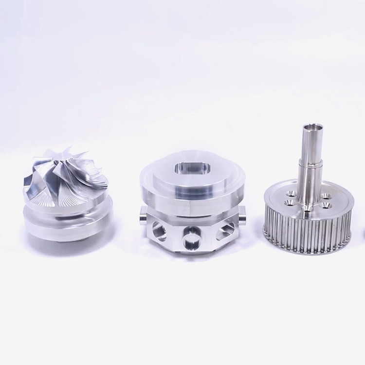
Best For: Machining smaller to medium-sized parts, as the table’s load capacity is a limiting factor. Excellent for complex, multi-sided components like impellers, turbine blades, and intricate molds.
H4: 2. Head/Head Configuration (Dual Rotary Head)
Here, both rotational axes are built into the spindle head.
How it works: The workpiece remains stationary on a standard table (or one with a single rotary axis). The spindle itself can swivel and pivot to achieve the necessary angles.
Typical Axes: X, Y, Z, B, C.
Best For: Machining very large or heavy parts, as the table does not need to move them rotationally. Ideal for large structural aerospace components or mold bases.
H4: 3. Table/Head Configuration (Hybrid)
This is a versatile configuration where one rotational axis is on the table (typically a C-axis rotary table) and the other is on the head (typically a B-axis).
How it works: Combines the benefits of both styles, offering great flexibility for part size and complexity.
Typical Axes: X, Y, Z, B, C.
Best For: A wide range of part sizes and geometries, offering a balance between load capacity and accessibility. Common in general-purpose 5-axis machining centers.
H2: The Practical Power of Multi-Directional Machining
So, what does this ability to move in five directions actually enable? The benefits are transformative:
Single-Setup Machining: The most significant advantage. A complex part requiring features on five faces can be completed in one clamping. This eliminates cumulative errors from multiple setups, drastically improves accuracy, and reduces lead times.
Machining Complex Geometries: It allows the tool to maintain an optimal orientation to the part surface. This is critical for:
Organic/Freeform Surfaces: Aerospace blisks, marine propellers, sculptural forms.
Deep Cavities & Undercuts: Features that would be impossible for a straight tool to reach in a 3-axis setup.
Compound Angles: Holes or features drilled at non-orthogonal angles without special fixtures.
Improved Surface Finish & Tool Life: By tilting the tool, the effective cutting diameter at the point of contact can be optimized, allowing the use of shorter, more rigid tools. This reduces vibration, enables higher feed rates, and produces better surface finishes while extending tool life.
Enhanced Drilling Capabilities: With full 5-axis interpolation, the machine can perform “3D drilling” – positioning and drilling holes at any spatial angle in a single, smooth motion.
H3: Partnering with Expertise: Navigating 5-Axis Capabilities
Harnessing the full potential of 5-axis CNC machining requires more than just owning the machine. It demands deep engineering expertise, advanced CAM programming skills, and rigorous process control. This is where partnering with a specialized manufacturer like GreatLight CNC Machining Factory becomes a strategic advantage.
With over a decade of experience and a facility equipped with advanced 5-axis CNC machining centers, GreatLight Metal has moved beyond simply operating machines to mastering the art of multi-axis manufacturing. Their team understands how to select the optimal machine configuration for a given part, program efficient and collision-free toolpaths, and ensure that the theoretical precision of the equipment is consistently realized in every finished component. Their ISO 9001:2015 certified quality management system provides the framework that ensures this complex process yields reliable, repeatable results.
Conclusion
To definitively answer the question, which directions can a 5-axis CNC machine move? It moves linearly in the X, Y, and Z directions while simultaneously rotating around two additional axes (A, B, and/or C). This fusion of linear and rotational movement empowers manufacturers to approach a workpiece from virtually any angle in a single, coordinated operation. It breaks the constraints of traditional machining, enabling the production of parts with unprecedented complexity, accuracy, and efficiency. For projects demanding the highest levels of geometric freedom and precision, leveraging the multi-directional prowess of 5-axis CNC machining is not just an option—it is the definitive solution.
FAQ: Frequently Asked Questions About 5-Axis CNC Directional Movement
Q1: Is 3+2 axis machining the same as simultaneous 5-axis machining?
No, they are distinct. In 3+2 machining (also called positional 5-axis), the two rotational axes position the workpiece at a fixed angle, and then machining proceeds with the three linear axes (like a 3-axis operation). In full simultaneous 5-axis machining, all five axes move in a coordinated, interpolated motion during the cut, which is essential for smooth, continuous complex surfaces.
Q2: What’s the difference between 5-axis and 5-sided machining?
5-sided machining typically refers to using a 3-axis machine with an indexable rotary table (like a 4th axis). The part is rotated to different fixed positions to access different sides, but complex angled contours cannot be machined in a continuous path. True 5-axis allows for continuous machining of complex, non-orthogonal geometries.
Q3: What are the main challenges in programming for 5-axis machines?
The primary challenges include generating efficient, collision-free toolpaths, managing tool length and orientation to avoid gouging, ensuring smooth axis movements to prevent jerky motion, and post-processing the CAM data into machine-specific G-code that accurately translates the toolpath for the specific machine’s kinematic configuration.
Q4: For a new product prototype with some angled features, do I always need 5-axis machining?
Not necessarily. A skilled manufacturing partner like GreatLight CNC Machining Factory can analyze your design. Sometimes, angled features can be achieved with 3-axis machining using clever fixturing or 4-axis indexing. They can advise on the most cost-effective and technically suitable solution, whether it’s 3-axis, 5-axis, or even additive manufacturing, to meet your prototype’s requirements.
Q5: How do I choose a supplier for a 5-axis machining project?
Look beyond the machine brand. Evaluate:
Technical Expertise: Experience with similar part geometries and materials.
Software & Programming Capability: Advanced CAM systems and simulation tools.
Quality Systems: Certifications like ISO 9001 and in-house metrology for verification.
Collaborative Approach: Willingness to engage in Design for Manufacturability (DFM) feedback.
Full-Process Support: Ability to handle post-processing (e.g., anodizing, painting) for a streamlined supply chain.



















