
What Is a Spindle on a CNC Machine?
A spindle is the rotating assembly that holds the cutting tool and feeds it speed and torque. This page explains how it works, where its limits sit, and how to read spindle specs before you approve a process.
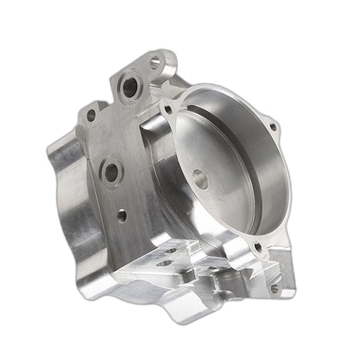
How the Spindle on a CNC Machine Turns Rotation Into a Cut
The spindle on a CNC machine is the rotating shaft assembly that clamps the cutting tool and drives it into the workpiece. A motor turns the shaft, the shaft holds the tool holder, and the tool holder holds the cutter. Each interface adds a small amount of error, so the whole chain decides how close the finished surface lands to the programmed path.
Cutting happens because the tool edge moves faster than the material can deform. Surface speed (m/min or sfm) comes from spindle RPM multiplied by tool diameter. Feed per tooth decides chip thickness. If either number is wrong, the tool rubs instead of cutting, and heat goes into the part and the tool rather than into the chip.
The spindle also has to resist force. Radial load from a side-milling cutter pushes the shaft sideways; axial load from a drill pushes it along its own axis. Bearings, housing stiffness and drawbar tension all work against that movement. When stiffness is low, the tool deflects, the wall tapers, and chatter marks appear on the floor of a pocket.
So the spindle is not just a motor. It is a stiffness, speed and accuracy package. Change one of those three and the parts you can hold to ±0.005 mm change with it.
Speed, Torque and the Power Curve
Spindle speed is quoted in RPM, usually as a range such as 0–24,000 RPM. Torque is quoted in N·m and falls as speed rises. Most spindles reach constant power in the middle of their range, so a 12,000 RPM cut and a 20,000 RPM cut may deliver very different torque at the tool.
Aluminium wants high speed and modest torque. A Ø6 mm three-flute carbide end mill in 6061-T6 runs well at 12,000–18,000 RPM with a chipload of 0.05–0.10 mm per tooth. Titanium and Inconel want the opposite: low surface speed, high torque, heavy coolant. A high-RPM spindle with a small torque window will stall in Ti-6Al-4V before it reaches a useful cutting speed.
Small tools need high RPM to reach a sane surface speed. A Ø1 mm drill at 6,000 RPM is running about 19 m/min, which is slow for aluminium. At 20,000 RPM the same drill reaches roughly 63 m/min and the chip clears properly. This is why micro-machining lives or dies on spindle speed.
The practical rule: match the spindle to the smallest tool and the hardest material in the job. If those two pull in opposite directions, split the work across two machines. We run 16 simultaneous 5-axis centers for complex geometry and 127 high-precision CNC machines in total, so a mixed-material job can be routed to the right spindle instead of pushing one machine past its curve.
Taper, Runout and Tool Holding
The taper is the cone that centers the tool holder in the spindle nose. Common sizes are BT30, BT40, HSK-A63 and HSK-E50. Bigger tapers carry more torque and resist bending better; smaller tapers change tools faster and spin higher. A BT40 nose will not fit a BT30 machine, and the wrong pull stud stops the tool change.
Runout is the total indicated movement of the tool tip when the spindle turns. It is usually quoted in μm at a set distance from the nose, for example 5 μm at 100 mm. Runout stacks from the spindle bearing, the holder, the collet and the cutter. A 3 μm spindle with a worn collet can still cut with 15 μm of runout at the tip.
Drawbar force holds the holder in the taper. Too little force and the holder creeps under heavy cuts; too much and the taper wears. Heat shrink holders and hydraulic holders give better runout than a standard collet chuck, which matters for reaming, boring and fine finishing.
Check runout with a dial indicator on a ground test bar before a tight-tolerance job. If the reading is above the machine spec, clean the taper, replace the collet, and re-check. Most runout complaints trace back to a chip in the taper, not a worn bearing.
Belt, Direct-Drive and Integral Motor Spindles
A belt-driven spindle uses a separate motor and a belt. It is cheap to service, delivers strong low-speed torque, and is common on older vertical mills. Its limit is speed: belts stretch, vibrate and lose accuracy above roughly 8,000 RPM.
A direct-drive spindle couples the motor to the shaft without a belt. Speed climbs to 15,000–20,000 RPM, and the response is faster because there is less rotating mass. The trade-off is cost and heat, since the motor sits close to the bearings.
An integral motor spindle, often called a motorized spindle, builds the rotor onto the shaft inside the housing. There is no coupling at all. Speeds reach 24,000 RPM and higher, and acceleration is quick enough for dense 3D finishing passes. The bearing set becomes the weak point, and repair means sending the whole unit out.
Air bearings and ceramic hybrid bearings push runout below 1 μm for mirror finishing and hard milling. They also demand clean, dry air and a narrow load window. For general shop work, a well-kept steel or ceramic hybrid bearing set is the better value. For thin-wall finishing on aluminium, the extra stiffness of an integral spindle is worth the cost.
What 3-Axis, 4-Axis and 5-Axis Spindles Change
On a 3-axis machine the spindle stays vertical and moves in X, Y and Z. The part must be re-fixtured for every new face. Each re-clamp adds setup error, often 0.02–0.05 mm, which eats into the tolerance budget before the cut even starts.
A 4-axis machine adds a rotary table, usually about A or B. The spindle can machine four sides in one setup. This is a good fit for shaft-like parts, connectors and any job with features on several faces around one axis. We run 12 four-axis mills and a Ø400 mm rotary table for this class of work.
A 5-axis machine adds a second rotary axis, so the tool can approach the part from almost any direction. The spindle reaches undercuts, deep pockets and compound angles without re-fixturing. Short, rigid tools replace long, flexible ones, which raises accuracy and cuts cycle time. We run 16 simultaneous 5-axis machining centers.
Five-axis does not fix a bad process. If the CAD model is dirty or the stock moves during the cut, more axes only add more ways to be wrong. Use 5-axis when the geometry demands it, and keep 3-axis for flat plates, covers and simple brackets.
Which Spindle Fits Which Job
Use this as a first filter, then confirm with a test cut.
| Job type | Best spindle choice | Why | Watch out for |
|---|---|---|---|
| Aluminium plate, flat faces | 3-axis, 12,000–18,000 RPM | High speed, low torque is enough | Thin floors may vibrate |
| Shaft with side holes | 4-axis, 8,000–15,000 RPM | One setup for four faces | Rotary table runout |
| Impeller, undercuts | 5-axis, 15,000–24,000 RPM | Short rigid tool, one setup | CAM programming time |
| Ti-6Al-4V bracket | Low-speed, high-torque, 4,000–8,000 RPM | Heat goes into the chip, not the edge | Tool wear and coolant flow |
| Mirror-finish mold insert | Integral motor spindle, runout under 2 μm | Low runout, clean finish | Clean, dry air and heat |
| Ø1 mm micro features | Integral motor spindle, 20,000 RPM+ | Surface speed and chip clearing | Small chipload, easy to rub |
| Deep pocket, long reach | High-stiffness taper, HSK-A63 or larger | Resists radial deflection | Chatter at long overhang |
The Short Version
Pick the spindle by the smallest tool and the hardest material in the job. If a part needs both high RPM and high torque, split it across two machines instead of asking one spindle to do both.
Spindle Questions Engineers Ask
Does higher spindle speed always give a better finish?
No. Finish depends on runout, chipload and tool geometry more than on RPM. Above a certain speed, vibration and heat can make the finish worse.
Find the speed where the tool cuts a clean chip, then stop. On 6061-T6, that is often 12,000–18,000 RPM with a 0.05–0.10 mm chipload per tooth, not the maximum the spindle can reach.
How does spindle runout show up on the part?
Runout makes one tooth cut deeper than the others. You see it as a size shift on a reamed hole, a spiral mark on a bore, or a finish that changes around the circumference.
It also shortens tool life, because one edge does most of the work. Measure the tool tip with a dial indicator before blaming feeds and speeds.
Can a worn spindle still hold ±0.005 mm?
Sometimes, but not reliably. Bearing wear raises runout and reduces stiffness, so the tool deflects more under load. The error appears as taper in a wall or a size drift across a batch.
If a machine used to hold tolerance and no longer does, check the spindle first. Measuring runout and drawbar force is faster than re-cutting the whole setup.
What spindle does a 5-axis job actually need?
A 5-axis job needs a spindle with enough stiffness to use short tools, plus a rotary axis pair that keeps the cutting point close to the pivot. Speed matters for aluminium; torque matters for titanium and steel.
The real question is tool access. If the geometry lets you use a rigid tool, a mid-range spindle will hold tolerance. If it forces long overhangs, no spindle speed will save the cut.
How is spindle heat managed?
Motorized spindles generate heat in the bearings and the motor windings. Most designs use an oil-air or water jacket to carry it away, plus a warm-up routine before the first cut.
Skipping the warm-up shifts the shaft length by a few μm, which is enough to move a tight tolerance. Run the spindle at low speed for a few minutes before finishing passes.
What materials run well on a high-speed spindle?
Aluminium alloys such as 6061, 7075 and 6082, plus brass, copper and most plastics, run well at high RPM. So do many stainless grades at reduced speed with good coolant.
Titanium, Inconel and hardened tool steel need lower surface speed and more torque. They cut best on a spindle with a wide torque window rather than a very high top speed.
Send Us Your Part and We Will Match the Spindle
Tell us the material, the tightest tolerance and the smallest tool in the job. We route it to the spindle that fits and quote within 12 hours.
12-hour quote100% inspectionNo minimum order
More Shop Notes From GreatLight
We publish setup notes, tooling trials and inspection data from the factory floor.











