
UAV Radiation Detector Brackets CNC
A detector bracket does two jobs at once: it carries the payload and it fixes the sensor's look angle. Both jobs are set by geometry, so the machining process decides how well the mission works. This page explains what that geometry has to hold, where 3-axis work stops being enough, and when a machined bracket is the wrong answer.
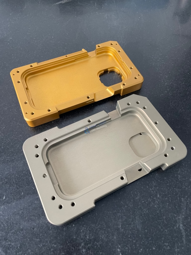
What the bracket actually controls
A radiation detector on a UAV is a mass at the end of a lever. Every gram of bracket sits far from the airframe's center of gravity, so bracket mass shows up twice: once as payload weight, once as a trim problem. Most detector heads used on small airframes weigh between 0.3 kg and 2 kg, which means a 150 g bracket is not a rounding error.
The second job is angular. Scintillation crystals and solid-state detectors are directional: count rate falls off as the source moves off the crystal axis. If the bracket tilts the detector 1° from the intended axis during a 40 m survey pass, the ground footprint shifts and the count map smears. Tight angular tolerance is not cosmetic here. It is the difference between a usable map and a set of numbers nobody trusts.
The third job is stiffness. A bracket that flexes under rotor vibration changes the detector's pointing angle at the same frequency as the blades. That modulation appears in the count data as noise you cannot filter out afterward, because you no longer know where the detector was looking.
So the drawing usually carries three numbers that matter more than the rest: mass budget, angular position of the detector mounting face, and flatness of the face that seats the detector. Everything else on the part is secondary.
- 1Mass budgetOften 80–200 g for a small detector head.
- 2Angular positionTilt of the detector face sets where the count map lands.
- 3StiffnessFirst mode should sit well above rotor and gimbal frequencies.
- 4Seat flatnessA rocking detector face injects pointing error directly.
Where 3-axis machining stops working
A detector bracket is rarely a flat plate with holes. Typical geometry includes a canted detector face, two or more mounting bosses at different angles, a cable channel that runs around a bend, and pockets cut into the arms to pull mass out. That is four features on five or six distinct faces.
On a 3-axis mill you reach each face by re-fixturing. Every re-clamp adds an error stack: vise repeatability, chip under a locating pin, a soft jaw that was cut yesterday. In practice a four-setup part drifts by 0.05–0.1 mm between features, and the angular relationship between the detector face and the airframe mounting holes drifts with it.
Five-axis machining holds the part in one clamping and rotates the tool around it. The angular relationships are cut into the part while it never moves, so the error stack collapses to the machine's own geometry. On our 16 simultaneous 5-axis centers that shows up as feature-to-feature position inside ±0.005 mm on a well-prepared blank.
There is a second benefit that is easy to miss. Sculpted arms and blended fillets need the tool to approach from an angle a 3-axis spindle cannot reach. Ball-end milling with the tool tilted keeps chip load even across a curved surface, so the scallop height stays consistent instead of blowing out at the ends of the pass.
That matters on a part that sees airflow. A rough blend on a bracket arm is a stress riser and a place where a burr will abrade a cable jacket over a hundred flights. A smooth, predictable surface is a maintenance item you never have to think about.
- 1One clamping on 5-axisFeature-to-feature error drops to machine geometry.
- 2Tilted ball-end millingEven chip load across a contoured arm.
- 3Fewer setupsLess handling, fewer chances for a dinged mounting face.
Material choice and what it does to the part
Most UAV detector brackets are cut from aluminium, and the two workhorses are 6061-T6 and 7075. 6061-T6 machines cleanly, takes anodizing evenly, and is forgiving on thin walls. 7075 gives roughly 60% more yield strength at similar density, which lets you cut the arm sections thinner for the same stiffness. It costs more and it is less friendly to anodize for corrosion, so it usually appears on brackets where mass really is the constraint.
Where the airframe sees salt spray or decontamination wash-down, 316L stainless and 17-4PH come into play. Both are heavier for the same stiffness, so they appear as small fittings rather than whole brackets. Titanium TC4 (Ti-6Al-4V) sits between them on mass and is used when the bracket also has to survive heat near a power module.
Magnesium AZ31B and AZ91D are the lightest option and are used on some airframes. The trade is corrosion control: magnesium needs a coating that survives handling, and any bare edge becomes a corrosion site. We machine it, but we ask what the wash-down procedure looks like before quoting it.
The material also sets the wall you can hold. A 1.5 mm aluminium wall is routine. A 1.5 mm magnesium wall with a 40 mm unsupported span will ring. On thin sections we usually leave a machined rib rather than push the wall thinner, because the rib costs less mass than the extra wall thickness it replaces.
- 16061-T6General-purpose, good anodizing, forgiving on thin walls.
- 27075Higher strength, thinner arms, harder to anodize for corrosion.
- 3316L / 17-4PHSalt spray and wash-down service, heavier per unit stiffness.
- 4Magnesium AZ31BLightest route, needs a coating that survives handling.
Finish, shielding and the small details
Anodizing is the default finish on aluminium brackets. Type II clear or black gives corrosion protection and a hard, non-conductive surface. If the bracket is part of a grounding path, we mask the contact pads or use conductive anodizing so the joint is not insulated by its own coating.
Hardcoat anodizing is worth the cost on parts that get handled every flight, because the coating resists the scratches that come from repeated install and removal. On magnesium, a chemical conversion coat followed by powder coat holds up better than anodizing alone.
Electroless nickel is common on stainless and steel fittings where wear resistance matters more than color. Bead blasting before coating gives a matte, uniform look and hides tool marks on cosmetic faces, though it also slightly changes the surface roughness reading.
One detail that gets forgotten: laser marking. Serial numbers, torque values and orientation arrows are marked directly on the bracket at a minimum character height of 1.5 mm, so a technician in the field can read the torque spec without a drawing. It is a small thing that prevents a large mistake.
- 1Masking for groundingConductive anodizing or masked pads keep the joint bonded.
- 2Hardcoat on handled partsResists scratches from repeated install cycles.
- 3Laser markingTorque values and orientation arrows at ≥1.5 mm character height.
Inspection: proving the bracket before it flies
A machined bracket is only as good as the evidence that it matches the drawing. For detector brackets, three checks carry most of the risk: the angle of the detector mounting face, the position of the airframe mounting holes relative to that face, and the flatness of the seat.
We check the first two with a coordinate measuring machine against the datum scheme on the drawing. Seat flatness gets a surface check plus a light-blue fit test on a granite plate when the drawing calls for it. Reports are available on request, and 100% inspection happens before shipment: raw material check, in-process monitoring, final inspection.
Surface roughness is specified where it matters. A detector seat usually wants Ra 0.8–1.6 μm so the detector sits without rocking. Non-critical outer faces are fine at Ra 1.6–3.2 μm as machined. Only sealing faces or optical seats justify Ra 0.2–0.8 μm, and they cost more because they need a separate finishing pass.
For anyone building a first article, our sample center runs the part through the same inspection path as production, so the report you see at prototype stage is the same format you get at volume.
- 1CMM on anglesDetector face angle and hole position to datum.
- 2Seat flatnessSurface check plus fit test when specified.
- 3Roughness by functionRa 0.8–1.6 μm on seats, as-machined elsewhere.
Machining route by bracket geometry
Match the route to how many distinct faces carry a tolerance.
| Bracket situation | Recommended route | Why |
|---|---|---|
| Flat plate, 1 face, few holes | 3-axis milling | Lowest cost, no angular stack to manage |
| Detector face canted to mount plane | 4-axis or 5-axis | Angle cut in one clamping, no re-fixture drift |
| Pockets plus two angled bosses | 5-axis simultaneous | All faces reached without moving the part |
| Thin sculpted arms, blended fillets | 5-axis ball-end milling | Even chip load, consistent scallop height |
| One-off form check before cutting | 3D printing | Validates fit and cable routing only, not stiffness |
| Salt-spray service, small fitting | 316L or 17-4PH on 4-axis | Corrosion resistance with tight hole position |
When to machine, when not to
If the detector face sits at an angle to the airframe mount and the drawing carries an angular tolerance, machine it on 5 axes and pay for the setup. If the bracket is a flat plate holding a non-directional sensor, a 3-axis part or a printed prototype is enough. Machining a part that has no angular requirement just adds cost.
Questions engineers ask before ordering
Can the bracket be printed instead of machined?
For form and fit checks, yes. A printed bracket lets you confirm cable routing, bolt access and detector clearance before you commit to metal.
For flight hardware, printed polymer does not hold the stiffness or the bolted-joint preload. Where the detector angle matters, machined aluminium or titanium is the safer route.
How tight does the detector seat really need to be?
Tighter than most drawings imply. If the seat rocks, the detector tilts, and the tilt shows up as pointing error in the count data.
Ra 0.8–1.6 μm on the seat face and flatness within 0.02 mm across the seating area covers most detector heads. Ask for a fit check on a granite plate if the head has a large flat base.
What is the lightest practical bracket material?
Magnesium AZ31B or AZ91D is the lightest option we machine. It costs you a coating step, because bare magnesium corrodes quickly.
For most airframes, 7075 with thin arms and a machined rib is the better balance. It gives most of the mass saving without the corrosion maintenance burden.
Does the finish affect grounding or shielding?
Yes. Anodizing is an insulator, so a bracket that is part of a ground path needs masked contact pads or conductive anodizing.
Tell us which faces carry the ground path on the drawing. Masking is cheap if it is planned in, and awkward if it is discovered at assembly.
What do you need to quote a detector bracket?
A 3D file, a 2D drawing with the datum scheme and the tolerances that matter, material, finish, and quantity. A note on the detector mass and where it mounts helps us sanity-check stiffness.
We return a quotation and a free DFM analysis within 12 hours. Production can start within 24 hours of approval, and parts ship in 3–5 days.
How is confidentiality handled?
Uploads are secure and confidential. An NDA is available on request before you send drawings.
We hold ISO 27001:2022 for information security alongside ISO 9001:2015, IATF 16949:2016 and ISO 13485:2016.
Send us the bracket drawing
Upload a 3D file and a 2D drawing and we will return a quotation plus a free DFM analysis within 12 hours.
12-hour quote100% inspectionNo MOQ
GreatLight elsewhere
We publish setup notes, tooling trials and inspection data from the factory floor.











