
Soil Nutrient Probe Shaft Machining
This page explains how a slender sensor shaft is actually cut: which materials survive soil chemistry, where concentricity really has to land, and why surface finish decides whether the probe still reads correctly after two seasons in the ground. Written for design engineers and buyers who need to judge a quote, not just accept one.
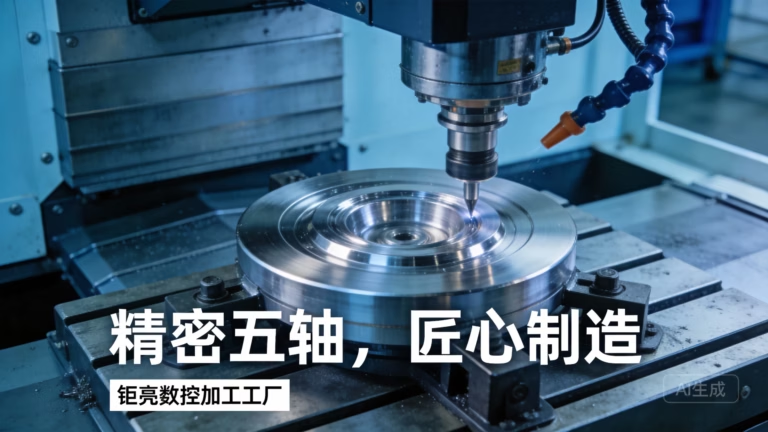
What makes a probe shaft hard to machine
A soil nutrient probe shaft looks simple on a drawing: a stepped cylinder with a threaded end and a bore down the middle. In the machine it is one of the least forgiving parts we run. Length-to-diameter ratios of 15:1 to 25:1 are normal, so the workpiece deflects under its own cutting load before the tool ever complains.
The features stack in a way that punishes setup error. An outer diameter carries the sensor reference, an internal bore carries the wiring or the sensing element, a thread takes the tip or the connector, and a flat or keyway sets angular alignment. If the bore and the outer diameter are not concentric, the sensing element sits off-axis and the reading drifts with rotation.
Wall thickness is the second constraint. A Ø12 mm shaft with a Ø6 mm bore leaves 3 mm of wall. That is enough for stiffness but not enough to absorb vibration from a long overhang. We plan the toolpath around the wall rather than around the outside diameter, because the wall is what fails first.
Tolerance on a production drawing is usually written as ±0.005 mm on the critical diameters and ±0.05 mm on everything else. Tightening the whole drawing does not help. It raises cost and cycle time without changing how the probe performs in soil.
Material choice decides the cutting strategy
Material selection for soil nutrient probe shaft machining is driven by soil chemistry first and machinability second. Acidic or heavily fertilized soil attacks 303 stainless faster than 316L, so the cheaper free-machining grade is often the wrong economy. We machine 304, 316, 316L, 17-4PH and 420 regularly, and each one behaves differently at the spindle.
303 machines cleanly and holds thread form well. It also contains sulfur, which helps chips break but leaves the surface slightly less corrosion resistant. For a probe that stays in the ground for years, 316L is the safer default even though it costs more cycle time.
Titanium TA2 and TC4 (Ti-6Al-4V) appear on drawings where weight or galvanic compatibility matters. Both work-harden quickly. Light radial passes, sharp tooling and steady coolant flow keep the cut below the hardened layer. Push too hard and the next pass skims over a surface harder than the insert.
17-4PH in the H900 condition gives high strength and good corrosion resistance, but it is abrasive. Inconel shows up occasionally for high-temperature soil monitoring. It demands low surface speed and high-pressure coolant, and it will double the cycle time of a 316L part of the same shape.
Concentricity and runout on long thin shafts
The number that matters most on a probe shaft is not the diameter tolerance. It is the runout between the internal bore and the outer reference diameter. When those two features sit on different axes, the sensing element rotates off-center and the reading changes with every turn of the probe.
On a shaft under 300 mm long we hold ±0.005 mm on critical diameters and keep total indicated runout inside 0.01 mm. Past 300 mm the shaft starts to sag between centers, and the practical limit loosens. We measure runout on a surface plate with a height gauge or on a rotary table with an indicator, not by eye.
The usual root cause of runout is not the machine. It is the number of setups. Turning the outside, flipping the part, boring the middle and then milling a flat gives four chances to build error into the part. Reducing setups removes error rather than compensating for it.
A Ø400 mm rotary table handles the round features, and a 5-axis center with 4,000 × 400 × 150 mm travel covers long shafts in one fixturing. Five-axis is not free. It costs more per hour than a three-axis lathe. The trade only pays when the part has enough features to justify it.
Surface finish and thread quality in stainless
Surface finish is a corrosion control, not a cosmetic detail. A turned surface is a series of peaks and valleys. Soil moisture, fertilizer salts and stray current collect in the valleys and start pitting there. The smoother the surface, the fewer places for that to begin.
We hold Ra 0.8–1.6 μm as a standard machined finish and Ra 0.2–0.8 μm where the drawing calls for it. Going below Ra 0.2 μm on a long shaft is possible with polishing, but it adds handling risk. Any dent from handling wipes out the gain.
Thread quality is the other common failure point. Stainless galls. A thread cut with a dull insert tears rather than shears, and the torn flank seizes the first time someone assembles the tip. Sharp tooling, correct pitch diameter and a light pass at the end prevent most of it.
Electroless nickel and passivation are the two finishes we apply most on probe shafts. Passivation restores the chromium oxide layer after machining and costs little. Electroless nickel adds hardness and a uniform coating inside bores, which plating struggles to reach evenly.
How we run a probe shaft order
- 1Design review and DFMWe check wall thickness, length-to-diameter ratio and datum scheme, then send a DFM note with the quote within 12 hours.
- 2Material verificationMill certificates are checked against the drawing before the bar sees a machine. Grade mix-ups are cheaper to catch here.
- 3First-operation turningRough and finish the outer profile between centers or in a collet, leaving stock only where the second operation needs it.
- 4Bore and threadDrill, ream and thread in the same setup where possible so the bore stays referenced to the outer diameter.
- 5Milling and flatsKeyways and flats are cut on a 4-axis or 5-axis center to keep the angular position tied to the same datum.
- 6FinishingPassivation, electroless nickel or bead blasting, depending on the corrosion requirement and the drawing callout.
- 7Final inspectionCritical diameters, runout and thread gauging on 100% of parts. Reports are issued on request.
Material trade-offs for probe shafts
Machinability rated for turning and threading on slender stock.
| Material | Corrosion in soil | Machinability | When it fits |
|---|---|---|---|
| 303 stainless | Moderate | Excellent | Short-life or lab probes |
| 304 stainless | Good | Good | General field use |
| 316 / 316L | Very good | Fair | Long-term buried sensors |
| 17-4PH (H900) | Good | Fair | High-strength tips and threads |
| TA2 / TC4 titanium | Excellent | Poor | Weight-critical or galvanic pairs |
| Inconel | Excellent | Very poor | High-temperature monitoring |
Which route fits your shaft
If the part is a short stepped shaft with one thread, a turned part on a lathe with a second op is the right call and costs the least. If it has a deep bore, a keyway and a long body, run it on a 5-axis center in one fixturing and accept the higher hourly rate. Choose 316L when the probe stays buried; choose 303 only when the probe is short-lived or lab-bound.
Common questions
What length-to-diameter ratio can you actually hold tolerance on?
Up to roughly 15:1 we hold ±0.005 mm on critical diameters without special support. Between 15:1 and 25:1 we use a steady rest or tailstock support and the runout budget grows.
Beyond 25:1 the shaft deflects under cutting force and we will tell you so at the DFM stage rather than quote a number we cannot repeat.
Do you machine the internal bore in the same setup as the outer diameter?
Whenever the geometry allows, yes. A single setup keeps the bore and the outer reference on one axis, which is the whole point of the tolerance.
Long shafts that exceed the spindle bore sometimes need a second operation. In that case we indicate the part back in against the finished outer diameter, not against a rough face.
Which stainless grade should I specify for a buried probe?
316L is the safe default for long-term burial. It resists chloride and fertilizer attack better than 303 or 304, and the low carbon content limits sensitization if the part is ever welded.
303 is fine for a probe that is inserted, read and pulled in the same season. It machines faster and threads more cleanly, which shows up in the price.
Can you hit Ra 0.2 μm on a Ø10 mm shaft?
Yes, on the outer diameter. We reach Ra 0.2–0.8 μm with fine turning plus polishing when the drawing requires it.
The limit is handling. A polished Ø10 mm shaft marks easily, so we protect it in transit and ask that assembly happens with soft jaws.
How do you keep stainless threads from galling?
Sharp tooling, correct pitch diameter and a light finishing pass. We also gauge threads rather than trusting the insert to be on size.
Where the mating part is also stainless, a dry-film lubricant on assembly prevents most seizure in the field.
What inspection data comes with the parts?
All parts are inspected before shipment, and reports are available on request. That includes critical diameters, runout and thread gauging.
If your quality system needs first-article documentation or material certificates, tell us at the quote stage so we build it into the schedule.
Send us your probe shaft drawing
Upload a STEP file or a 2D drawing and we return a quotation with a free DFM analysis within 12 hours. No minimum order quantity, from one prototype to 10,000+ parts.
12-hour quote±0.005 mm tolerance100% inspectionNDA on request
More from the shop floor
We publish setup notes, tooling trials and inspection data from the factory floor.











