
Professional Sheet Metal Fabrication OEM: How Bending, Welding and Finishing Interact
This page explains what separates a professional sheet metal fabrication OEM partner from a general job shop. It is written for design engineers and sourcing staff who must judge whether a supplier can hold a flat pattern, control springback, and keep finish consistent across a production run.
In this article
- 1
- 2
- 3
- 4
- 5
- 6
What the OEM Relationship Actually Changes
A job shop receives a drawing and returns parts. A professional sheet metal fabrication OEM partner owns part of the process before the drawing is final. That means the flat pattern, the bend sequence, the weld fixture and the finish order are decided together, not one after another. When those four decisions are made in isolation, the first article can pass and the thousandth part can fail.
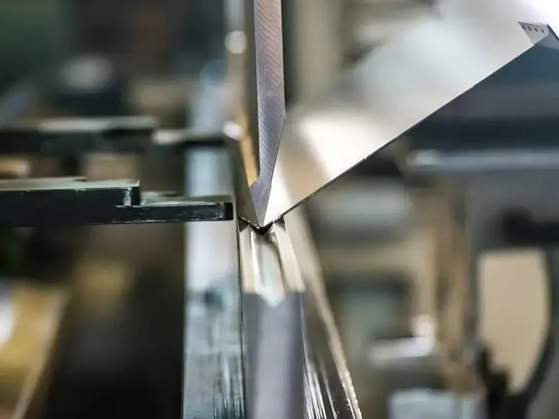
The physical reason is that sheet metal behaves differently from machined billet. A bent flange does not stay where the press brake puts it; it springs back by an amount that depends on material, thickness, bend radius and grain direction. A welded seam pulls the panel out of flat. A punched hole near a bend line distorts when the bend forms. None of these effects show up in the CAD model.
So the OEM relationship is mostly about information flow in both directions. We send back a flat pattern and a bend table. You confirm which faces are datums, which holes are functional, and which surfaces will be visible after assembly. Two or three exchanges at that stage remove most of the rework later.
This also changes how tolerance is assigned. Blanket tolerance notes on a title block force the supplier to guess. A professional partner will ask which dimensions are functional, then apply tight control where it matters and looser control where it does not. That is how cost stays proportional to function.
- 1Flat pattern ownershipThe supplier should generate and verify the developed length, not the customer.
- 2Datum agreementPick one primary datum face and reference inspection to it.
- 3Bend sequence reviewConfirm the order of bends before tooling is committed.
Springback, Bend Allowance and the Limits of Sheet Metal
Springback is the elastic recovery of the material after the punch releases. For 6061-T6 aluminium at 2 mm thickness, a 90° air bend typically returns 1° to 3° depending on the die opening. Mild steel returns less. Stainless 304 returns more and work-hardens as it goes, so a second bend on the same flange needs a different compensation than the first.
Bend allowance and bend deduction are the arithmetic that converts a formed part into a flat pattern. The neutral axis does not sit at the mid-thickness; it shifts toward the inside of the bend. If the flat pattern is calculated with a fixed K-factor for every material and thickness, holes will land off position after forming. We calculate per material and thickness, then verify with a first article.
There are hard limits worth knowing before you design. A minimum inside bend radius of roughly one material thickness is safe for most mild steel and aluminium; tighter radii risk cracking, especially across the grain. Hole-to-bend distance should be at least 2.5 times material thickness plus the bend radius, or the hole will pull oval.
Hemming, embossing and louvers add their own constraints. A closed hem on 1.5 mm stainless needs a pre-bend and will show a witness line on the outside face. If the outside face is cosmetic, say so early. We can move the hem to a hidden edge or switch to a riveted overlap instead.
- 1Air bend vs bottomingAir bending needs less tonnage and tolerates more material variation.
- 2Grain directionBend across the grain where possible to reduce cracking risk.
- 3Thickness variationHot-rolled sheet can vary ±0.1 mm and shifts the developed length.
Why Welding and Finishing Are One Problem, Not Two
Welding heat distorts a fabricated assembly. A 300 mm long TIG seam on 2 mm aluminium can pull the panel 1 mm to 2 mm out of flat. If flatness is called out after welding without a straightening step, that callout will not be met. The usual fix is a weld fixture plus a planishing or press-straightening operation before the finish is applied.
Finish choice interacts with the joint. Anodizing is an electrochemical process, so it colors the weld filler differently from the parent metal on 6061. The seam will show as a visible line even after clear anodizing. Powder coating hides the seam but adds 60 µm to 120 µm of thickness, which can interfere with close-tolerance mating faces and threaded inserts.
For a professional sheet metal fabrication OEM program, the finishing step should be sequenced by function. Mask threaded holes and mating surfaces before coating. Apply laser marking after the finish, not before, or the mark will be buried. Minimum legible character height for laser marking is 1.5 mm.
If a cosmetic class A surface is required, bead blasting followed by a consistent batch anodize gives the most repeatable result. Mixing parts from different production lots in one anodize bath is the most common cause of a color mismatch that only appears after assembly.
- 1Mask before coatingThreads, dowel holes and electrical ground pads.
- 2Mark after finishLaser marking under powder coat loses contrast.
- 3Batch anodize togetherSame lot, same bath, same rack position where possible.
Reading a Sheet Metal Tolerance Callout Correctly
Sheet metal drawings often carry a general tolerance of ±0.1 mm and a separate note for hole position. Those two numbers mean different things. The ±0.1 mm applies to a formed feature measured from a datum. Hole position depends on the flat pattern, the punch accuracy and the bend compensation, so it accumulates more error.
In practice, a formed sheet metal part on a 500 mm panel is normally held to ±0.1 mm on bend-to-bend dimensions and ±0.2 mm on hole-to-hole across a formed feature. Tighter than that is possible on smaller parts, but it requires hard tooling and an inspection plan, and the cost curve turns sharply.
This is where a machining partner helps. GreatLight runs 127 high-precision CNC machines alongside sheet metal capacity, with 16 simultaneous 5-axis machining centers and a 4,000 mm maximum processing size. When a bracket needs a machined boss, a reamed bore or a flat mounting face after forming, it is machined in the same plant instead of being shipped to a second supplier.
Tolerance is a claim that has to be inspected to be real. Every part goes through raw material check, in-process monitoring and final inspection before shipment, with reports on request. If a drawing calls ±0.05 mm on a formed feature, we will say so rather than accept it and sort it out later.
- 1Functional vs non-functionalOnly the dimensions that locate other parts need tight control.
- 2Datum stabilityA bent flange is a poor datum; use a flat face.
- 3Inspection planAgree on what is measured, on what instrument, at what frequency.
Judging a Supplier Before You Send the PO
Ask for the flat pattern and bend table on the first quote. A supplier that only returns a price has not engaged with the geometry. A supplier that returns a developed length, a bend sequence and two or three DFM questions has. That difference predicts how the production run will go more reliably than any brochure.
Check what happens after forming. If the part needs anodizing, plating, powder coating or laser marking, and the supplier subcontracts all of it, you inherit the coordination risk. Finish consistency problems are usually scheduling problems between two vendors, not chemistry problems.
Ask how the first article is measured and what happens if it fails. A clear answer names the instrument, the fixture and the rework path. A vague answer usually means the part will be re-cut and re-bent until it passes, which resets the tolerance stack without telling you.
Finally, check the commercial terms that create friction later. No minimum order quantity means a single prototype and a 10,000+ part run can be quoted on the same process route, which keeps the prototype representative. Uploads are kept confidential and an NDA is available on request. Both matter when the drawing is not public yet.
- 1Ask for the flat patternIt is the clearest signal of real process ownership.
- 2Map the finish chainKnow who anodizes, who coats, who marks.
- 3Agree the first-article planInstrument, fixture and acceptance criteria in writing.
Which Fabrication Route Fits Your Part
Match the process to the quantity, geometry and tolerance the part actually needs.
| Route | Best for | Watch out for |
|---|---|---|
| Laser cut + press brake | Brackets, panels, 1–10,000+ parts | Springback on thick or high-strength sheet |
| CNC machining from plate | Machined bosses, tight bores, flat faces | Higher material waste than forming |
| Stamped hard tooling | Very high volume, stable design | Tooling cost and long design freeze |
| Welded assembly | Enclosures, frames, large cabinets | Weld distortion and finish mismatch |
| Sheet metal + CNC hybrid | Formed body with machined interfaces | Needs one supplier for both operations |
The Rule We Apply
If your part is flat, formed and cosmetic, choose a supplier that owns bending, welding and finishing under one roof. If your part needs machined interfaces after forming, choose a supplier that also runs CNC in the same plant. Splitting those two operations across vendors is where tolerance and finish problems come from.
Questions Engineers Ask Next
How tight can a formed sheet metal dimension realistically be?
On a panel up to about 500 mm, bend-to-bend dimensions are normally held to ±0.1 mm and hole-to-hole across a formed feature to ±0.2 mm. Tighter values are achievable on small parts with hard tooling and a defined inspection plan, but the cost rises quickly and the process becomes less forgiving of material variation.
If a dimension is functional, tell us and we will control it. If it is only a reference, leave it loose. Blanket tight tolerances across an entire drawing are the most common reason a quote comes back higher than expected.
Does the material grade change the bend radius I can use?
Yes. 5052 and 6061 aluminium in the O and T4 conditions bend more easily than T6. Stainless 304 work-hardens, so a tight radius on a second bend is riskier than on the first. 7075 aluminium is generally not a good candidate for tight-radius forming.
A practical starting point is an inside radius of one material thickness for mild steel and most aluminium, and 1.5 times thickness for stainless. Send the grade with the drawing and we will confirm before tooling is set.
Why does my clear anodized part show a visible weld line?
Anodizing is electrochemical. The weld filler and the parent metal respond differently to the bath, so the seam colors differently even when both are 6061. This is not a defect in the weld; it is a property of the process.
If the seam must disappear, the options are to move it to a hidden face, grind and planish it flat before finishing, or switch to powder coating, which covers the joint with 60 µm to 120 µm of film.
When is a job shop the right choice instead of an OEM partner?
When the part is simple, the design is frozen, the tolerance is loose and the finish is as-formed or a single basic operation. A job shop will quote that quickly and the price will be competitive.
The OEM relationship earns its cost when the design is still moving, when several operations have to agree with each other, or when the part has to be repeatable across a long production run. That is where flat pattern control and finish sequencing pay for themselves.
What do you need to return a quote and DFM feedback?
A 3D model or a dimensioned drawing, the material grade, the required finish, and the quantity range including the prototype quantity. If a face is cosmetic or a hole is a datum, say so. Those two facts change the process route more than anything else on the print.
Quotation and free DFM analysis come back within 12 hours. Production can start within 24 hours after approval, and parts typically ship in 3–5 days.
Can you handle both the formed body and the machined inserts?
Yes. GreatLight runs sheet metal fabrication alongside 127 high-precision CNC machines, including 16 simultaneous 5-axis machining centers, with a maximum processing size of 4,000 mm. Formed parts that need a machined boss, a reamed bore or a flat mating face are machined in the same plant.
This removes the tolerance stack that appears when the formed part travels to one vendor and the machining to another, and it keeps the finish sequence under one schedule.
Send the Drawing, Get the Process Route
Quotation and free DFM analysis within 12 hours, no minimum order quantity, and 100% inspection before shipment.
12-hour quoteNo MOQ100% inspectionNDA on request
More Process Notes
We publish setup notes, tooling trials and inspection data from the factory floor.











