
Chinese Rapid Tooling Manufacturing: How Bridge Tooling Is Actually Made
This page explains the process behind chinese rapid tooling manufacturing: which parts suit CNC-cut tooling, where the accuracy limits sit, and when a hard steel mold is the better call. Written for design engineers and sourcing leads who need to judge a quote, not read a brochure.
In this article
- 1
- 2
- 3
- 4
- 5
- 6
- 7
- 8
Key takeaways
What chinese rapid tooling manufacturing actually means
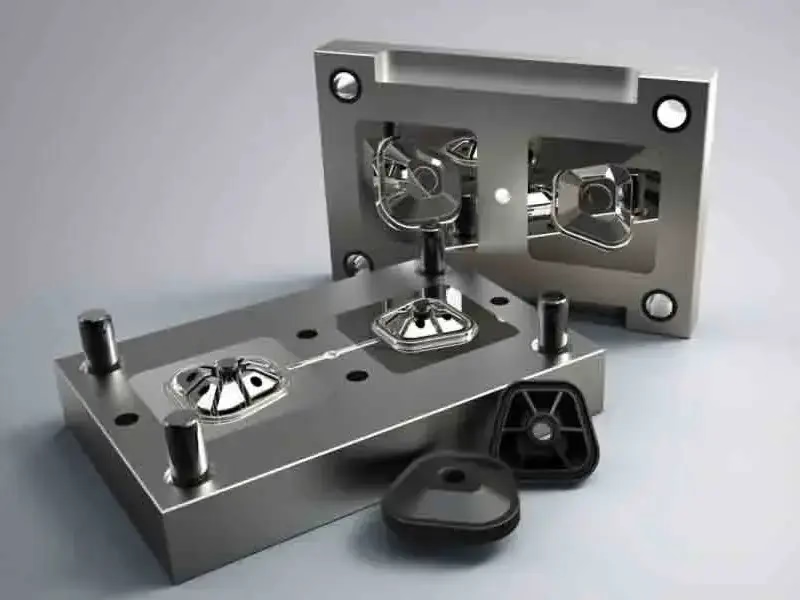
Rapid tooling is a family of methods for building a mold or forming die in days instead of months. In China the common version is hybrid: the mold base and frame are CNC-machined from standard plate, the cavity inserts are cut on 3-axis or 5-axis mills, and only the deep ribs or sharp internal corners go to EDM. The result is a tool that can run a few hundred to a few thousand shots, not a million.
The word rapid describes the schedule, not the geometry. A tool cut this way still holds the part's nominal dimensions, draft angles and shut-offs. What it does not have is a hardened, nitrided cavity with a balanced cooling layout behind it. P20 or 718 plate is typical for the cavity, and 1.2344 (H13) shows up when the resin is glass-filled or the run is longer.
That distinction matters at the drawing stage. A bridge tool made from pre-hardened plate will wear at gates and sharp corners. If your part has a 0.5 mm rib or a knife-edge shut-off, plan for insert replacement rather than a long life. Engineers who treat the first tool as a wear item get fewer surprises than those who treat it as a production asset.
So the practical question is not whether the tool is precise. It is whether the tool's expected life matches the number of parts you need before the hard tool lands. Answer that and the rest of the specification usually writes itself.
The four routes and where each one stops working
There are four routes in common use, and they fail in different places. CNC-cut aluminum is the fastest and cheapest for low cavity pressure. You get good surface off the tool, but aluminum galls and dents, so ejector wear shows up early. It suits 50 to 500 shots of ABS, PP or PC.
Pre-hardened steel plate, usually P20 or 718, is the workhorse. It machines cleanly, takes a polish to a SPI B-1 finish, and holds up to roughly 5,000 shots with reasonable care. This is the route most engineers mean when they say bridge tooling. Add a hardened insert at the gate and the wear problem moves to a manageable place.
Printed inserts come next. SLM maraging steel or a filled photopolymer can produce conformal cooling channels that a mill cannot reach. Conformal cooling cuts cycle time on thick sections, sometimes by a third. The catch is porosity and surface finish. A printed cavity usually needs finish machining on the sealing faces, so it is a hybrid step, not a shortcut.
Soft tooling closes the list. Silicone molds and vacuum casting give you 20 to 50 parts with almost no tool cost, but dimensional repeatability drifts and the material menu is narrow. Use it to check fit and feel, not to validate a tolerance stack.
Where the tolerance really comes from
A ±0.005 mm cut on the insert does not give you a ±0.005 mm molded part. Shrinkage, warpage and gate position dominate the final number. ABS shrinks about 0.5 to 0.7 percent, PP runs 1.0 to 2.5 percent depending on grade and flow direction. If you quote a molded tolerance without naming the resin and the wall thickness, the number is fiction.
The tolerance you can trust is the one on the steel. On our 5-axis centers we hold ±0.005 mm on cavity and core inserts, with surface finish from Ra 0.2–0.8 μm on sealing faces up to Ra 1.6–3.2 μm on non-critical walls. Those numbers are measurable before the tool ever sees a press, and that is the point: inspect the steel, then predict the part.
Shut-off faces deserve their own note. They are where the two halves meet, and they carry the flash risk. A shut-off that is too tight will gall and crack; too loose and you get flash on every shot. A 0.02 to 0.05 mm interference band on a vertical shut-off is a normal starting point, adjusted for the resin's viscosity.
Draft is the other quiet failure. One degree on a textured wall is not enough. Add 1.5 degrees per 0.025 mm of texture depth, or the part scuffs on the way out and you blame the resin.
How a hybrid tool gets built in one shop
The build sequence matters more than any single machine. First comes DFM. We check wall thickness, draft, undercuts and gate location against the CAD, then return a marked-up model plus a quote within 12 hours. Most rework on a rapid tool traces back to a skipped DFM step, not to a machining error.
Next, the mold base is cut from standard plate on a 3-axis mill, and the cavity and core inserts go to the 5-axis centers. Our floor runs 16 simultaneous 5-axis machining centers, 12 four-axis mills and 27 three-axis machines, with a maximum processing size of 4,000 mm. A Ø400 mm rotary table covers most round cores in one setup.
Then EDM finishes the corners and ribs the cutter cannot reach. Wire EDM handles the shut-off profiles and ejector holes; mirror-spark EDM brings sharp internal corners to size. If the design has conformal cooling, the printed insert arrives from our SLM line and gets its sealing faces skimmed before assembly.
Before the tool ships, we run it. A short sampling run confirms fill, ejection and the first-off dimensions. Production can start within 24 hours of a released design, and parts ship in 3–5 days on standard jobs. Every tool leaves with inspection reports on request.
How to judge a chinese rapid tooling manufacturing supplier
Ask what the tool is made from before you ask the price. A supplier who quotes P20 for a 30 percent glass-filled nylon part is either guessing or hoping. The material choice tells you whether they read your drawing.
Ask which machines cut the cavity. A shop that subcontracts its 5-axis work loses control of the schedule and the tolerance. Our 127 high-precision CNC machines include 16 simultaneous 5-axis centers and 16 mill-turn centers, all under one roof in Dongguan, with a second plant in Singapore.
Ask how the tool is inspected. A CMM report on the cavity insert is worth more than a promise about the molded part. We inspect 100 percent before shipment, covering raw material check, in-process monitoring and final inspection, and we hold ISO 9001:2015, IATF 16949:2016, ISO 13485:2016 and ISO 27001:2022.
Ask about change handling. A rapid tool will get modified. Design revisions are the norm, not the exception, and the shop's habit around them predicts how the program will go. There is no minimum order quantity here, so a single prototype and a 10,000-part run go through the same process.
Finally, ask about confidentiality. Uploads are secure and confidential, and an NDA is available on request for programs that need one before drawings move.
When rapid tooling is the wrong answer
Rapid tooling stops making sense at two boundaries. The first is volume. If the program needs more than roughly 5,000 parts before the hard tool would have been ready, the cycle time and maintenance cost of a bridge tool start to outweigh the speed advantage. Run the arithmetic on scrap rate before you commit.
The second is material. Glass-filled and mineral-filled resins, high-temperature PEEK and PEI, and anything with abrasive filler will chew through a soft cavity. The tool may survive the sampling run and fail in the pilot batch. For those parts, go straight to a hardened insert or a full production mold.
There is a third, softer boundary: geometry that depends on tight cooling control. Thick sections, long thin cores and parts with cosmetic Class A surfaces need balanced cooling that a rapid tool rarely has. You can still build the tool, but expect longer cycle times and a higher chance of sink marks.
None of this is a reason to avoid the route. It is a reason to name the expected run, the resin and the cosmetic requirement before the first cut. Those three answers separate a tool that pays for itself from one that creates a second problem.
Tool material versus expected run
Shot counts are planning ranges, not guarantees.
| Route | Typical shots | Lead time | Watch out for |
|---|---|---|---|
| Aluminum cavity, CNC | 50–500 | 3–7 days | Gate wear, ejector dents |
| P20 / 718 plate | 500–5,000 | 7–15 days | Sharp corners, thin ribs |
| Printed maraging insert | 1,000–10,000 | 10–20 days | Porosity, sealing faces |
| Silicone / vacuum cast | 20–50 | 2–5 days | Dimensional drift |
| Hardened H13, full mold | 100,000+ | 25–45 days | Cost, change orders |
Our verdict
If you need 50 to 5,000 parts, a defined resin and a launch date measured in weeks, cut the inserts and go. If you need 100,000 parts, abrasive filler or Class A cosmetics on thick walls, skip the bridge tool and pay for hardened steel once.
Questions engineers ask us
Can a rapid tool hold ±0.05 mm on the molded part?
Usually yes, on a stable resin and a simple wall, if the shrinkage is accounted for in the cavity. The steel is cut to ±0.005 mm, so the tool is not the limiting factor.
The limit is process variation. Gate location, packing pressure and mold temperature all move the part. On a first-run tool, expect to spend one or two sampling rounds dialing those in before the dimension settles.
How many shots before the tool needs repair?
On P20 or 718 plate with an unfilled resin, 5,000 shots is a reasonable planning number. Gates and sharp corners wear first, so a hardened gate insert is a cheap upgrade.
Aluminum cavities wear faster. Treat 500 shots as the point where you should expect to touch up the gate area.
Is printed tooling as accurate as CNC-cut steel?
The printed insert is not the accuracy problem; its sealing and shut-off faces are. Those get finish machined after printing, and the final tolerance comes from the mill, not the printer.
What printing buys you is conformal cooling. If your part has a thick section that runs hot, that is where the gain shows up, in cycle time.
What do you need from us to quote?
A 3D model plus a drawing with critical dimensions, the resin grade, the expected annual volume and the cosmetic requirement. A STEP file alone works for DFM, but the resin and volume drive the tool material.
We return a quotation and a free DFM analysis within 12 hours. There is no minimum order quantity.
Can you handle both the tool and the molding?
Yes. The tool is built here and sampled here, so the first-off dimensions come from the same shop that cut the cavity. That removes the usual argument between the toolmaker and the molder.
Parts ship in 3–5 days on standard jobs, and inspection reports are available on request.
How do you protect our design?
Uploads are secure and confidential, and we will sign an NDA before drawings change hands if your program needs one. We hold ISO 27001:2022 for information security.
Tooling and fixtures built for your program are not reused for anyone else.
Send the model, get a tooling answer
Upload your part and we will return a quote, a DFM mark-up and a tool material recommendation within 12 hours.
12-hour quote100% inspectionNo MOQNDA on request
Follow our shop floor
We publish setup notes, tooling trials and inspection data from the factory floor.











