Based on comprehensive analysis of the processing characteristics and burr characteristics of shell parts, the technology of active burr removal in mechanical processing was proposed, and combined with actual production, we explored methods and deburring tools suitable for typical hull parts such as holes, surfaces and grooves. , carry out step-by-step control from the source of the processing process, transform passive deburring into active deburring, thereby realizing mechanized processing of burr removal, reducing the workload and improving the product processing quality.
01
Preface
The shell parts have the characteristics of complex structure and high processing precision. With the application and promotion of advanced manufacturing technologies, competition in the manufacturing industry is becoming more and more fierce.[1]Customers’ quality requirements and product processing efficiency are also increasing day by day, but our deburring methods are still limited to the use of abrasive tools such as files, bonded grinding wheels, shovels, wire brushes, needle brushes, abrasive belts and sharpening stones. Manually remove burrs from product processing parts. Currently, this method falls far short of meeting customer needs. The secondary factory has gradually understood that deburring is an important step in improving the cleanliness of the hull. How to improve the deburring effect and quality has become an important question. Deburring has a significant impact on the product. The quality of the final processing and the quality of the appearance are crucial. According to surveys, active deburring technology can be used as an important link in cleanliness control.[2]eliminates burrs generated during processing, improves the processing quality of parts, and avoids cleanliness problems caused by burrs[3]。
02
Traditional deburring methods
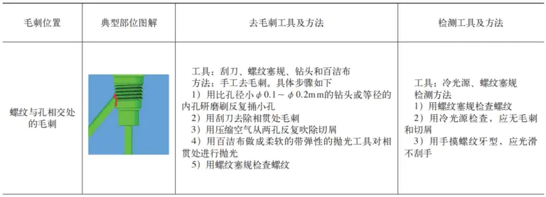
During the manufacturing process of hull parts, burrs or burrs will always occur at the intersection of machined surfaces.[2]. The main purpose of deburring is to remove thorns or burrs formed around the processing portions of housing parts. For hull parts, the main machining features are holes, faces, and grooves, and burrs mainly exist on the edges of these features. The traditional deburring method is relatively backward and has low processing efficiency, which directly affects the product delivery cycle and processing quality. The traditional method of removing hull thread burrs is shown in Table 1.
Table 1 Traditional Methods for Removing Hull Thread Burrs

03
Classification of shell burrs
According to the requirements for the appearance and size of burrs during the cutting process (see Figure 1), burrs during the processing process are divided into micro-burrs, small burrs and large burrs according to their size (see Table 2).

a) Appearance of the burr b) Size of the burr
Figure 1 Appearance and size of burrs when cutting
Table 2 Burr size classification

In Figure 1, H is the height of the burr, which is the maximum distance between the end surface of the part measured on the cross section and the cross-sectional profile of the burr. B is the thickness of the root of the burr, which is the burr; convex point measured on the end surface of the part. The distance between the ideal machined surfaces of the workpiece r is the radius of the burr root circle, which is one of the dimensions of the cross section of the burr measured on the cross section.
04
Mechanical deburring methods
Mechanical processing is the cause of burrs, and it is also the key point of burr control. In order to further improve the processing quality of burr removal and ensure the processing efficiency of parts, CNC machining is adopted, which is more conducive to ensuring the processing quality of shell parts. According to the burr size division method, follow the principle of burrs from large to small and from small to none.[3]Perform check and removal step by step.
The basic principles of shell burr control: firstly, large burrs generated during processing should be eliminated, and the generation of small and micro burrs should be reduced, so as to reduce the workload of burr removal in the later stage, secondly, cutting; the tools should be sharp during processing, so that the cutting does not produce large burrs during the process. When large burrs occur, the tool should be replaced in time to ensure that the size of the burrs is within a controllable range. During processing, certain processing principles should be followed to ensure that the direction of the burrs is in a certain direction, parts suitable for removal. The specific methods are as follows.
(1) The holes are processed first, and then the casing is mainly processed. Burrs often appear inside the holes or on the edge of the processed surface. For this type of processing, the hole can be processed first, then the surface can be processed to get less processing and no burr on the surface.[4]。
(2) Adjust the processing sequence for intersecting or intersecting hole systems, burrs usually appear at the junction of the two holes. The principle of controlling this type of burrs is to adjust the processing sequence so that the burrs are generated in a place suitable for observing the burrs and easily removing them.
(3) Changing the tool path for vertical milling will cause rapid wear of the cutter teeth and poor quality of the machined surface. Uphill milling does not have the phenomenon of tooth slippage in uphill milling, the degree of work hardening is greatly reduced, and the quality of the machined surface is higher.
(4) Optimize cutting parameters. Based on the tools and cutting parameters selected during hull parts processing, a CNC tool cutting parameter library is established to facilitate better on-site control of burr size and formation during processing. .
05
Deburring Methods for Typical Hull Part Features
Hull parts mainly consist of three types of features: holes, surfaces and slots.[5]formed by superposition. Hole elements are mainly used to provide hydraulic power and oil passages through the movement; Surface elements are mainly elements that connect holes and hole systems, forming the entity of hull parts. Slot elements are mainly connections between connection holes and hole systems; which are practical The oil lines are connected.
5.1 Method of deburring hole elements
(1) Classification of hole characteristics Holes are one of the most common characteristics of hull parts. According to the complexity of their processing, holes can be divided into simple hole systems and complex hole systems. A simple pore system is primarily composed of a single element that constitutes a pore and has a unique composition; a complex pore system is composed of several elements and has a complex structure.
(2) Features of hole cutters Hole features are mainly processed by drilling, and burrs mainly exist on the edges of hole features.[6]. The processing elements of single hole systems are unique, and the burrs are mainly concentrated in the parts where the holes are drilled and drilled (see Figure 2). Complex hole systems are composed of several processing elements and have various processing methods, as well as in the parts where the burrs are located. are generated are mainly concentrated in the hole system at the edge of each processing step.

a) Drill the burr b) Drill the burr
Figure 2 Drilling and Burr Removal
(3) Hole burr removal method ① Single hole burr removal method. The burrs of the single hole system are mainly concentrated in the drilled holes and drilled holes. The size of the drilled burrs is relatively small, and the burrs mainly exist on the machined surface of the workpiece. To eliminate these burrs, you can use a special rounding and chamfering tool, compile the corresponding processing program and remove the subsequently generated burrs. the hole is treated; drill out the burrs. The size is relatively large and the burrs are difficult to remove. According to the actual processing conditions of the shell, the residence time can be increased during the drilling process to ensure that the drill bit removes burrs. during the drilling process. ② How to remove burrs from complex hole systems. When processing complex holes, small features are often combined. Traditional processing methods use tools of different diameters depending on the processing characteristics of the workpieces, which can easily lead to the concentration of burrs generated during processing on different workpieces. Workpieces of different diameters cause the generation of larger burrs. In order to reduce the occurrence of such burrs, the processing characteristics of the shell parts are sorted out, and a special combination tool is designed (see Figure 3) to ensure that the hole system is processed and formed in one go. only improves the processing efficiency of the hole system, but also reduces the occurrence of generated burrs, thereby reducing the subsequent burr removal workload.

a) Characteristic hole system b) Tool
Figure 3 Complex hole system and its special combination tool
5.2 Methods for controlling and removing burrs from surface features
(1) Classification of surface characteristics Surfaces are the basic elements that make up hull parts. They mainly exist on the exterior surfaces of hull parts. Depending on their degree of regularity, they can be divided into regular planes and irregular planes. Regular planes mainly refer to planes with regular shapes and boundaries; Irregular planes mainly refer to curved surfaces during processing. This type of plan is uneven.[7]。
(2) Surface burr features Surface features are mainly processed by milling, and burrs are mainly generated on the edges. Once the regular plane has been processed, the burrs mainly exist at the edge of the plane; after the irregular plane is processed, the burrs mainly exist at the edge of the irregular plane. This type of burr is very concealed and difficult to remove during treatment.
(3) Surface burr removal method ① Regular surface burr removal method. Regular surfaces are usually processed along the contour of the workpiece with a face milling cutter, and the generated burrs are mainly concentrated on the edges of the surface. To eliminate such burrs, first use reverse milling to reduce the generation of large burrs, then compile a corresponding processing program, and use a tool with an arc to eliminate the burrs along the edge of the regular plane to ensure that the contact part is smooth and burr-free. ②How to remove irregular surface burrs. After the irregular surface is processed, the surface will have different heights. When using a tool with an R angle to remove burrs along the shape of the part, it is easy to overcut or fail to remove it. Design and manufacture special floating deburring tools for this purpose[8](See Figure 4). Use different deburring heads depending on the characteristics of the burr-producing parts (see Figure 5) to remove burrs along the processing edges of the parts until there are no more burrs or protrusions obvious.

Figure 4 Floating Deburring Tool

Figure 5 Deburring grinding head
5.3 Methods for controlling and removing groove burrs
(1) Classification of groove characteristics The groove characteristics are mainly concentrated on the surface of the workpiece and the connection between the hole system. Due to its strong concealment, it can be divided into ring grooves, special-shaped grooves and T-shaped grooves according to. to the functions performed (see Figure 6), where the annular groove[9]And the special-shaped grooves are mainly used to install rubber rings. Since there must be no leakage or oil seepage during the assembly process, the requirements for removing burrs on the edges are strict, and the edges must be uniform and smooth. T-shaped grooves mainly exist in the hole system and are mainly sealed by the hole system itself. However, since the rubber ring must pass through the edge of the T-shaped groove during the assembly process, the intersection of the T-shaped groove and the hole must be even and smooth, thus avoiding burrs that scratch the rubber ring.

a) Annular groove

b) Special-shaped groove

c) T-shaped slot
Figure 6 Classification of location features
(2) Method for removing characteristic groove burrs ① Method for removing special-shaped groove burrs. Since the processing of special-shaped grooves mainly relies on the position of points to control the groove structure of the workpiece, a special multi-step R tool is designed according to the processing characteristics of the workpiece (see Figure 7 after creating the special shaped groove). processed, tool R is used to move the part along the ring. The groove shape is processed to remove large burrs during the ring groove processing, and then a wool wheel is used to polish along the groove shape to ensure that the groove edge special shape is smooth and uniform. ②Annular groove burr removal method. When designing the annular groove, it must be concentric with the hole system or hole. The parts are sealed by the annular groove during assembly. Generally, the hole system and the annular groove are processed together. When using a machining center for processing, an R knife is designed and manufactured to mill along the shape of the workpiece in concentric circles to eliminate burrs generated during workpiece processing, then use a wool wheel to polish along the shape of the part. The ring groove to achieve the purpose of eliminating burrs. ③T-shaped burr removal method. T-shaped slots generally exist in the hole system. During processing, the hole system is processed first and the T-shaped slot is processed last. The burrs are mainly concentrated at the junction between the hole system and the T-shaped groove. In order to facilitate the removal of the burrs, a special groove tool (see Figure 8) is designed and manufactured. After processing the part, this tool is. used to carry out high-speed machining on the T-shaped groove. The edge is cut into 0.02~0.03mm to eliminate the burrs generated during processing.

Figure 7 Multi-stage R knife dedicated to deburring special-shaped grooves

Figure 8 Special grooving tool for deburring T-slots
06
Implementation effect
Through the deburring research on the holes, surfaces and grooves of the shell, quantitative control of the size of the burrs during the processing of the shell was achieved, the large burrs generated during processing were eliminated, and the small and micro-burrs have been reduced. or eliminated burrs, which fundamentally reduces the generation of burrs and achieves the purpose of reducing the workload of manual deburring. After checking on typical parts, it is ensured that the removal of large burrs reaches more than 90%, small and micro burrs are reduced by more than 20%, and the manual deburring workload is reduced by more than 30%.
07
Conclusion
This article analyzes the specific characteristics of different parts of the shell and adopts the method of first removing large burrs, and then removing small and micro burrs to achieve less or no burrs during the processing process. Through the implementation of the active deburring plane of the machining center, the burrs generated in the processing part are effectively eliminated, and the production bottleneck problems of irregular shell burrs, low treatment efficiency and poor cleanliness are resolved. Finally, the deburring methods for various typical hull parts were summarized and combined with actual production, we explored deburring methods and tools suitable for hull holes, surfaces and grooves, which solved the long and laborious problem of manual labor. deburring. Production efficiency has been greatly improved and good results have been achieved.
Daguang focuses on providing solutions such as precision CNC machining services (3-axis, 4-axis, 5-axis machining), CNC milling, 3D printing and rapid prototyping services.


