
Lifter Mold Internal Undercut Release
An internal undercut locks the part onto the core, so the part cannot simply be pushed off. This page explains how a lifter mold internal undercut release works, which angles and clearances hold up in production, and when a lifter is the wrong choice. Written for tooling and process engineers who have to sign off on the mechanism.
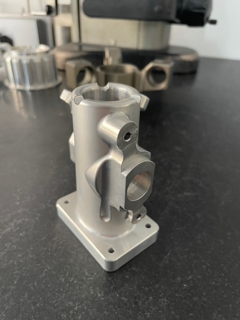
How lifter mold internal undercut release works
An internal undercut is any recess, tab, thread, or curved channel on the inside surface of a molded part that sits behind the core steel. The part cools and shrinks onto the core. Opening the mold along the parting line does not free that geometry, because steel still wraps it. Pull the part straight off and something has to give: the plastic cracks, the tab shears, or the core is gouged.
The fix is a side action that moves before the part leaves the core. For external undercuts, slides are the usual answer. Internal undercuts are harder because the working space sits inside the part envelope. A lifter, also called an angled ejector or horn pin, solves it by combining two motions in one component.
One end of the lifter is fixed to the ejector plate. The head sits in a pocket cut into the core and carries the undercut geometry. When the ejector plate pushes forward, the lifter rises along the ejection axis and, guided by an angled bore or guide rod, slides sideways at the same time. The head clears the undercut as the part moves up, so the feature is released without forcing it.
That dual motion is the whole mechanism. It is simple, but every parameter around it matters: lifter angle, stroke, head fit, guide clearance, and wear surface hardness. Get the angle wrong and the lifter binds or drags a mark across the part. Get the head fit wrong and flash appears on every shot.
Travel angle, stroke, and why 10°–15° is common
Lifter travel angle is measured against the parting line, not against the ejection direction. Most production tools run 10°–15°. A shallow angle gives more lateral travel per unit of ejector stroke, but it also increases the side load on the lifter and the guide bore. A steep angle reduces side load but needs a taller mold base to reach the same lateral travel.
Stroke has to cover two things: the undercut depth plus a safety margin, and the vertical lift needed to clear the core before the part is free. If the undercut is 2 mm deep and the angle is 12°, the lifter must slide at least 2 mm laterally before the head leaves the pocket. Add 0.5–1 mm of margin so small thermal shifts do not leave the head catching.
The head profile is not a copy of the part geometry. It is a copy plus clearance, typically 0.01–0.03 mm on the forming surfaces depending on resin and shrink. Too tight and the head galls against the pocket. Too loose and the undercut flashes. For glass-filled PA or POM, the clearance band narrows because wear opens it faster.
Check the angle against the mold base height before you commit. A 15° lifter on a deep core can push the base taller than the press daylight allows. In that case, reduce the undercut depth if the part function permits it, or move to a different mechanism instead of forcing a steep lifter into a tight stack.
Steel choice, hardness, and wear surfaces
Lifters are wear parts. They slide under load on every cycle, so material selection follows the same logic as any cam or slide. H13, 1.2344, and S7 are common choices, usually heat treated to 48–52 HRC. That hardness range holds the head profile without making the part brittle at the guide section.
Hardness alone is not enough. The guide bore and the sliding faces need a hardness differential or a low-friction coating, or the two surfaces will pick up on each other. Nitriding the bore or applying a thin PVD coating on the lifter shank keeps galling down. Lubrication grooves help on high-cycle tools.
If the resin is abrasive, such as glass-filled PA or PEEK with filler, expect the head forming surfaces to wear faster. Build in replaceability: make the head a separate insert where the geometry allows it, so a worn head can be swapped without scrapping the whole lifter body.
For small undercuts on low-volume tools, a softer steel may be acceptable if the cycle count is low. The trade is simple. Softer steel machines faster and costs less, but it will not hold ±0.005 mm on the head over a long run. Match the steel to the expected shot count, not to the drawing alone.
Machining the head: why 3-axis is usually not enough
A lifter head often carries blended radii, draft on multiple faces, and undercut angles that a straight tool cannot reach. Three-axis milling handles prismatic features well, but sculpted heads with compound angles need more setup positions or a multi-axis machine.
Four-axis work covers many heads where the geometry wraps around one axis. Five-axis simultaneous machining is the practical route when the head has compound curvature, deep blend radii, or a pocket that tucks under itself. On a simultaneous five-axis center, the tool stays normal to the surface through the blend, which keeps the radius consistent and avoids the faceting you get from repositioning a three-axis setup.
The tolerance that matters most is not the overall length. It is the head profile relative to the mounting face and the guide bore. If the head sits 0.01 mm off, the undercut depth changes on every part. Work from a single datum: mount face, guide bore, then head. Measure the head with the lifter in the same orientation it will sit in the plate.
Cooling near the head deserves attention during machining too. If the head runs hot, it grows and the clearances close. Where the geometry allows, a small cooling channel or a beryllium copper insert near the head keeps the temperature swing smaller and the clearances stable.
Lifter vs slide vs collapsible core
Pick the mechanism before you cut steel.
| Mechanism | Best for | Watch out for | Typical angle or range |
|---|---|---|---|
| Lifter | Internal undercuts inside the part envelope | Side load on guide bore | 10°–15° travel angle |
| Slide | External undercuts on the cavity side | Needs clear room outside part | Cams sized to stroke |
| Collapsible core | Internal threads and full rings | Higher tool cost, more maintenance | Segment travel 1–3 mm |
| Manual insert | Prototypes and very low volume | Cycle time, operator error | No angle limit |
| Bump-off | Shallow flexible undercuts | Only works with soft resins | Depends on part flex |
When to choose a lifter and when not to
If the undercut sits inside the part envelope and can be released with 10°–15° of angled travel, a lifter is the right call. If the undercut is a full internal thread or a closed ring, use a collapsible core instead. If the part is a prototype with no cycle pressure, a manual insert is cheaper than any mechanism.
Questions engineers ask about lifters
How do I know if the undercut is deep enough to need a lifter?
Measure the undercut depth against the resin's flex. Soft resins like PP or PE can often bump off undercuts up to about 0.5 mm without damage. Above that, or with any glass-filled or brittle resin, the part will crack or the tab will shear.
If the feature is a snap tab, a thread, or a boss with a back cut, plan for a mechanism. Guessing on a brittle resin is expensive.
Can a lifter handle more than one undercut?
Yes, within limits. A single lifter can carry a head that forms two nearby undercuts if they release along the same travel direction. The head becomes wider and the side load grows, so the guide bore has to be sized for it.
If the undercuts pull in opposite directions, use two lifters. Trying to release both with one angled head usually means one side drags.
What tolerance should the head be held to?
Forming surfaces on the head are usually held to ±0.005 mm relative to the mounting datum. Clearance to the pocket is a separate number, typically 0.01–0.03 mm depending on resin and shrink.
The tight tolerance is on the head profile, not on the shank. A looser shank with a tight guide bore is normal.
How often do lifters need replacement?
It depends on cycle count, resin abrasiveness, and lubrication. On a clean unfilled resin with good lubrication, a 48–52 HRC lifter can run for a long time before the head profile drifts out of tolerance. On glass-filled resin, expect much shorter intervals.
Design the lifter so it can be removed without pulling the core. That turns a long repair into a short one.
Does the lifter need its own cooling?
If the head forms a thick section or runs hot, yes. Thermal growth closes the clearances and the head starts to drag. A small cooling line or a beryllium copper insert near the head keeps the temperature swing smaller.
On thin-walled parts with short cycles, the lifter often runs cool enough without dedicated cooling.
What file formats help with quoting a lifter build?
Send the part model, the undercut region highlighted, and the mold layout if it exists. STEP and native CAD files both work. If you have a target resin and shrink rate, include it, because that drives the head clearance.
We review the geometry and send DFM feedback with the quotation.
Get lifter components machined to your mold layout
Send the head geometry and mold layout. We quote and return DFM feedback within 12 hours, and prototypes can ship in 3–5 days.
12-hour quote±0.005 mm tolerance100% inspection
More mold component engineering
We publish setup notes, tooling trials and inspection data from the factory floor.











